

![]()
Rolling Centers
Work-Driving Centers
Bevel Rolling Centers
Lathe Centers
information/other
information/other


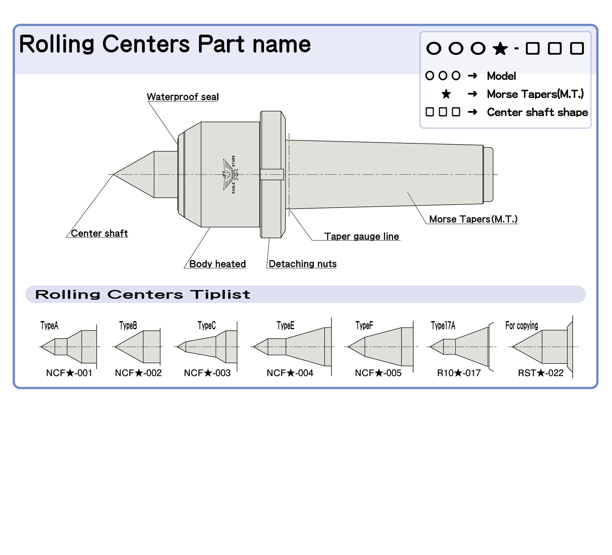
ROLLING CENTERS
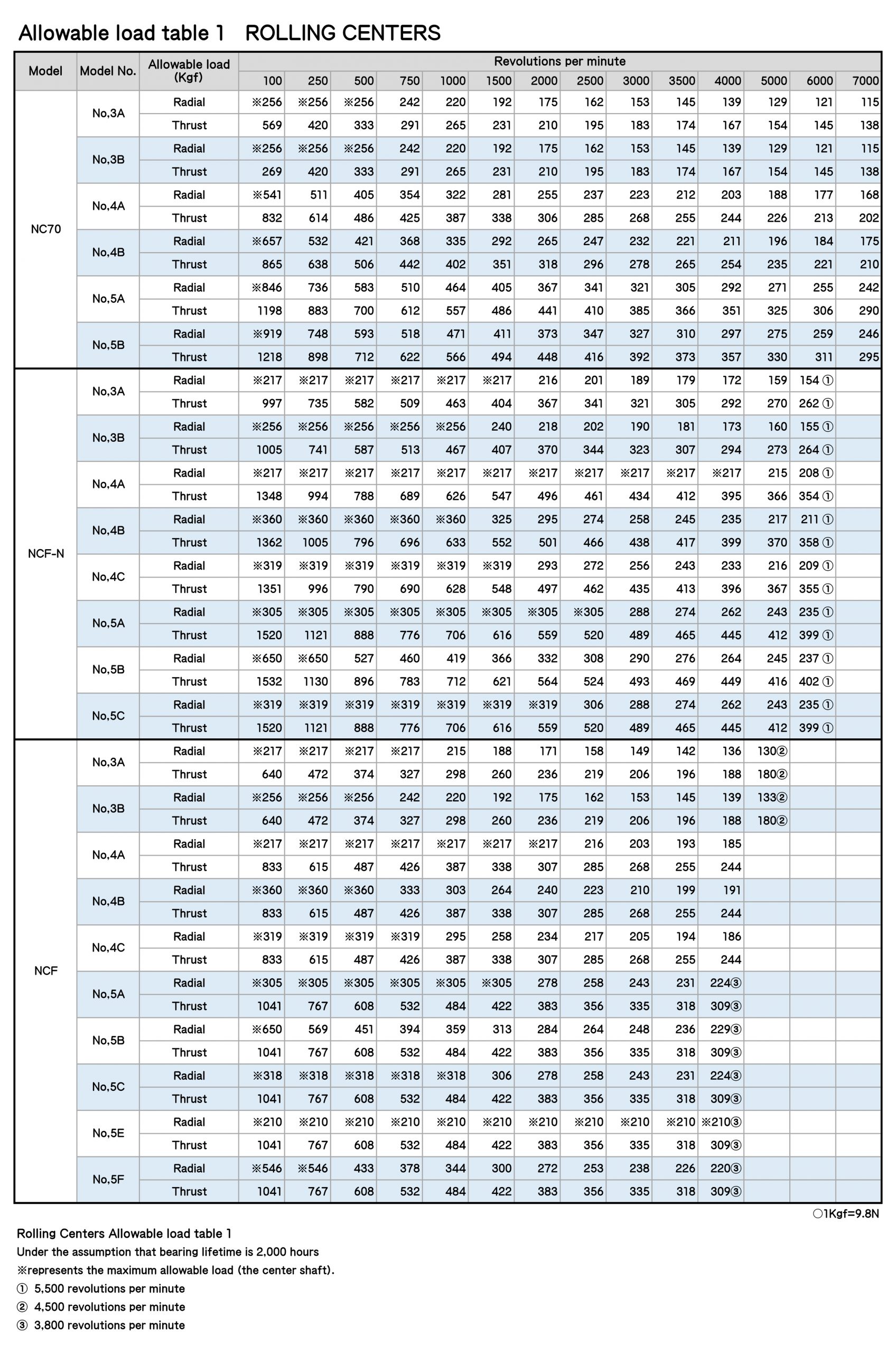
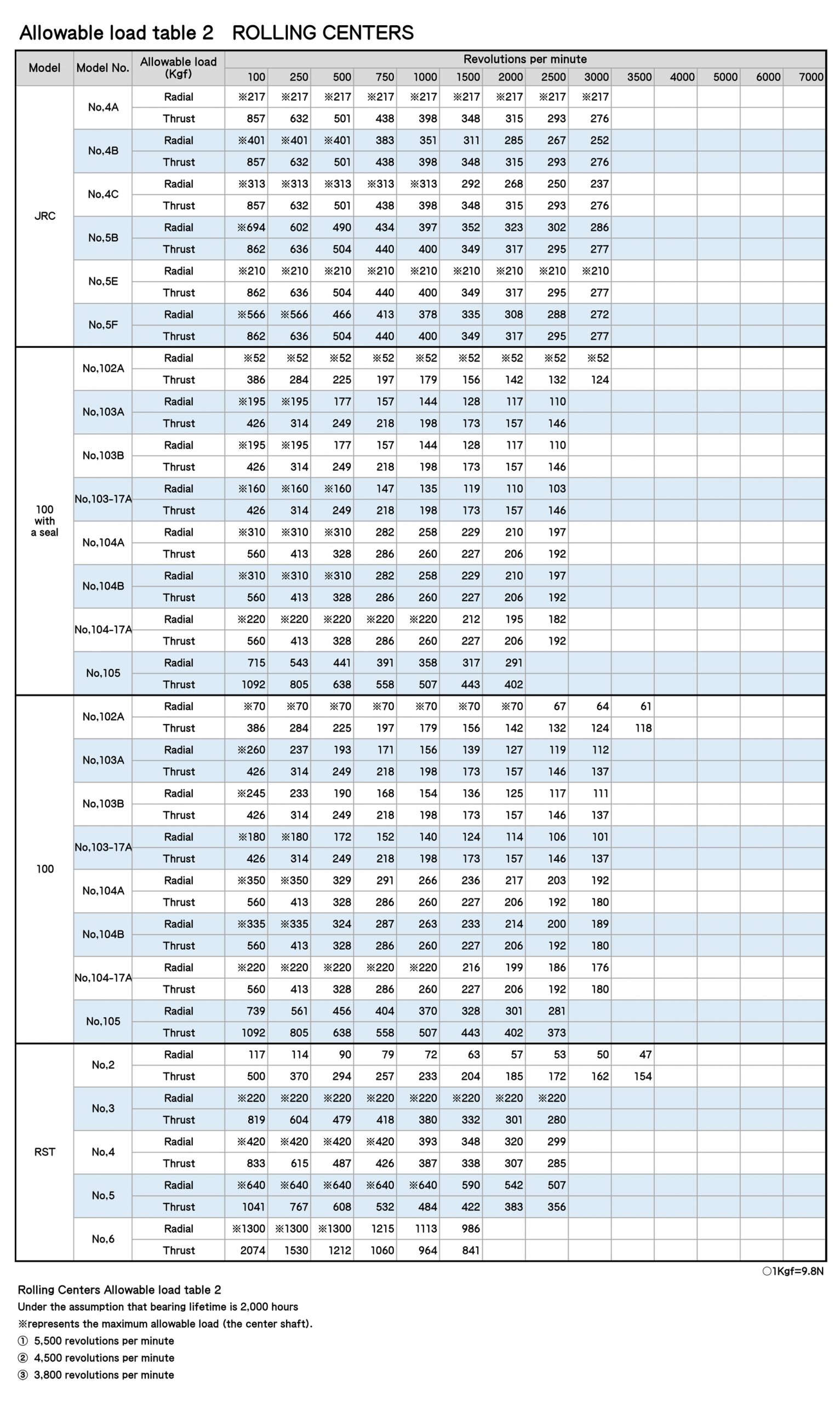
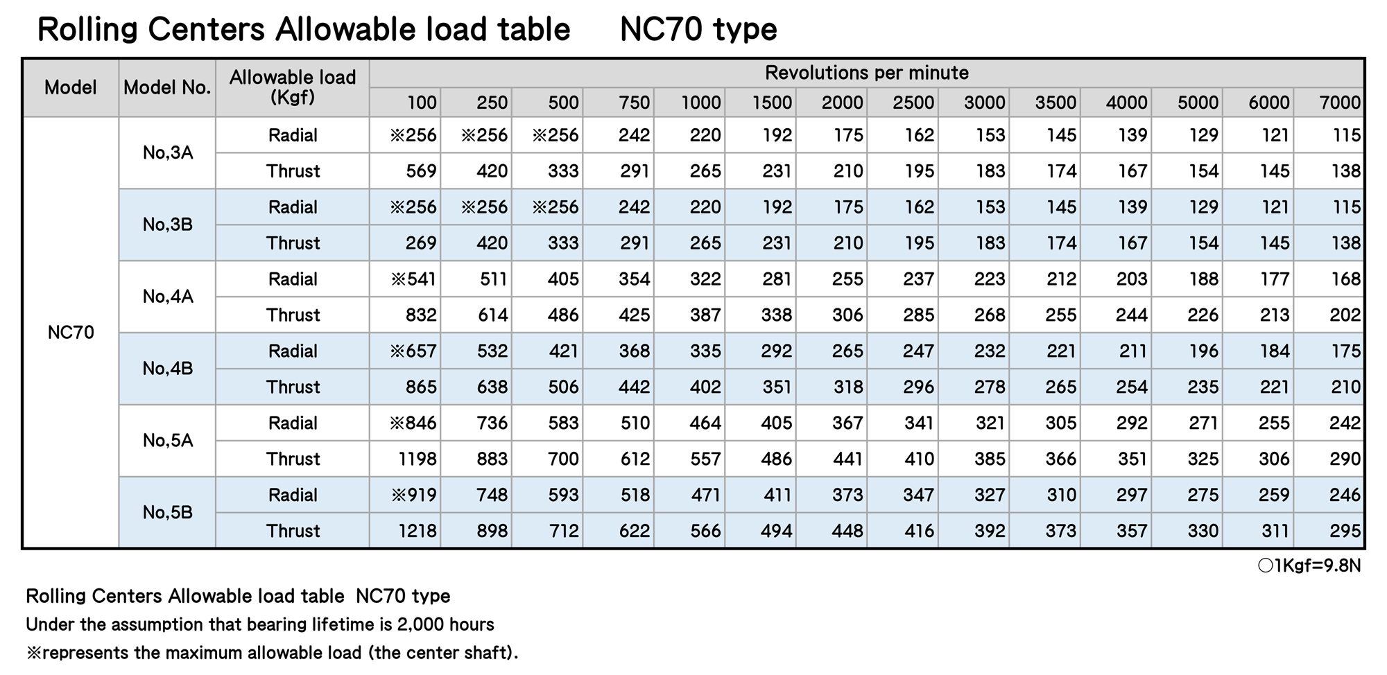
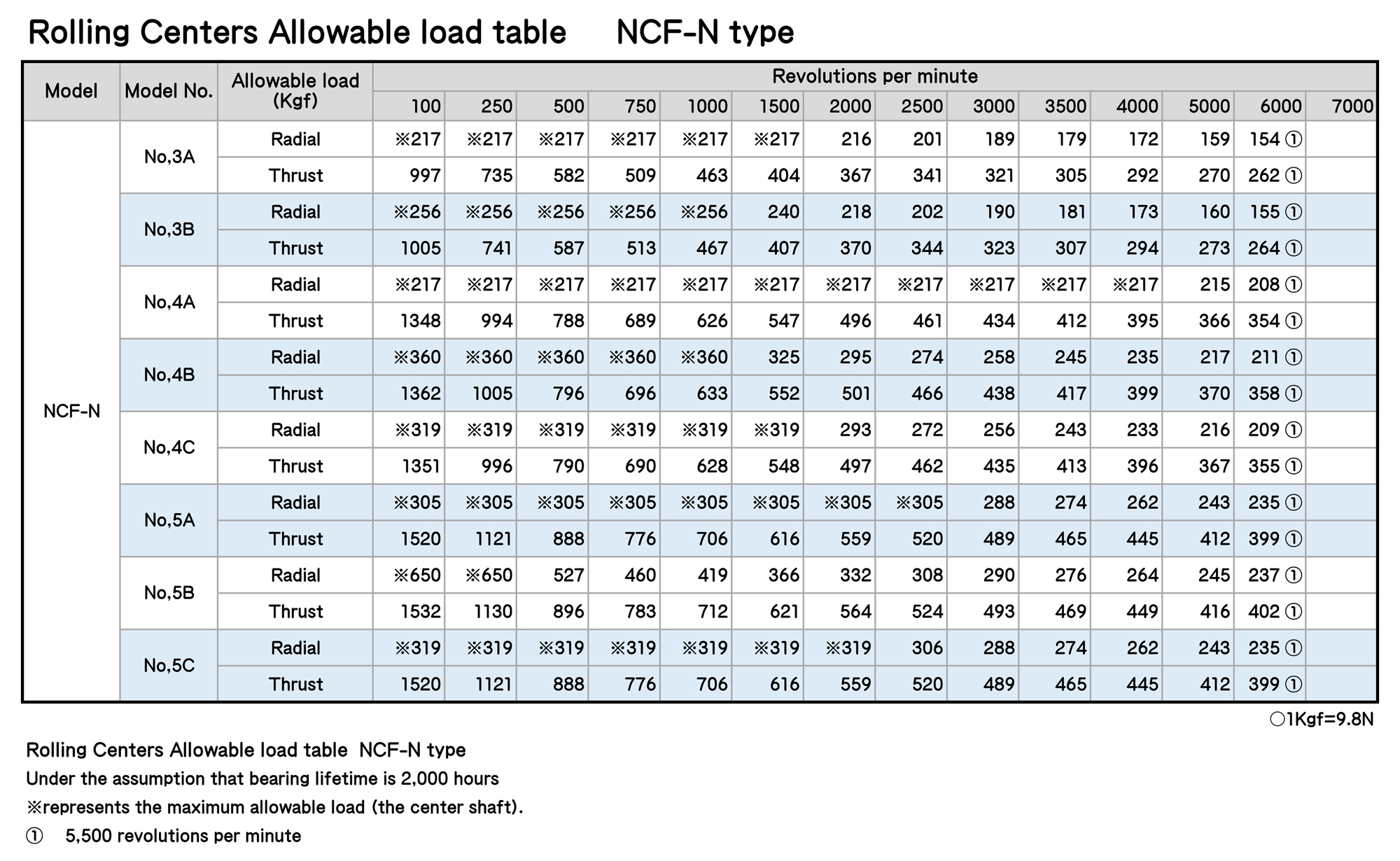
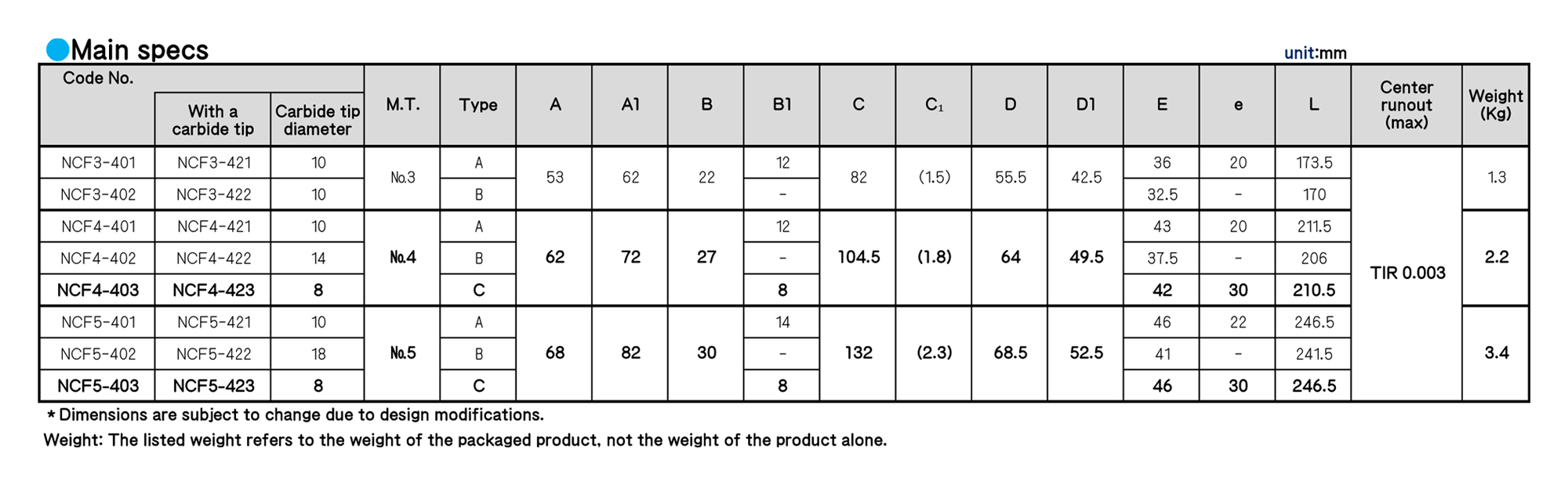
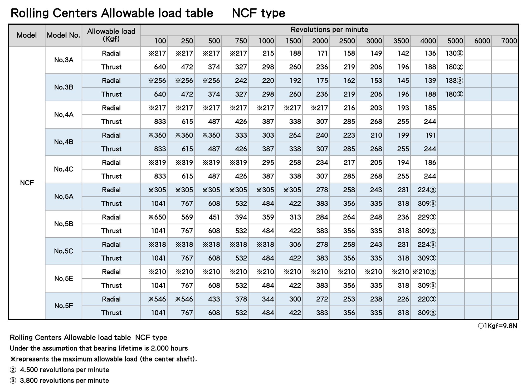
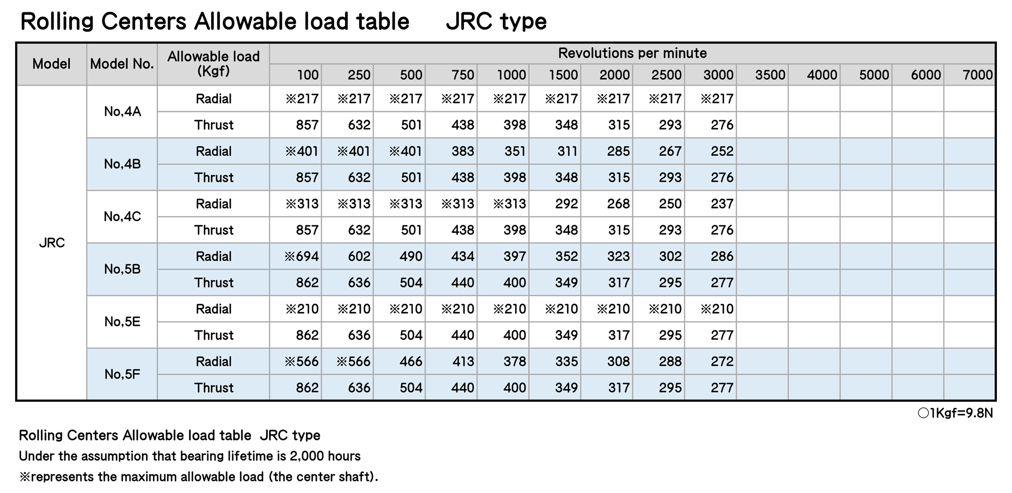
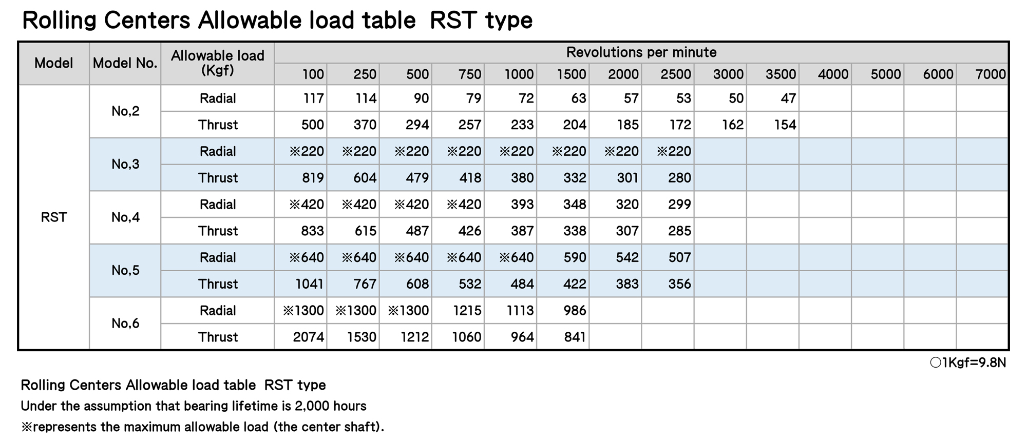
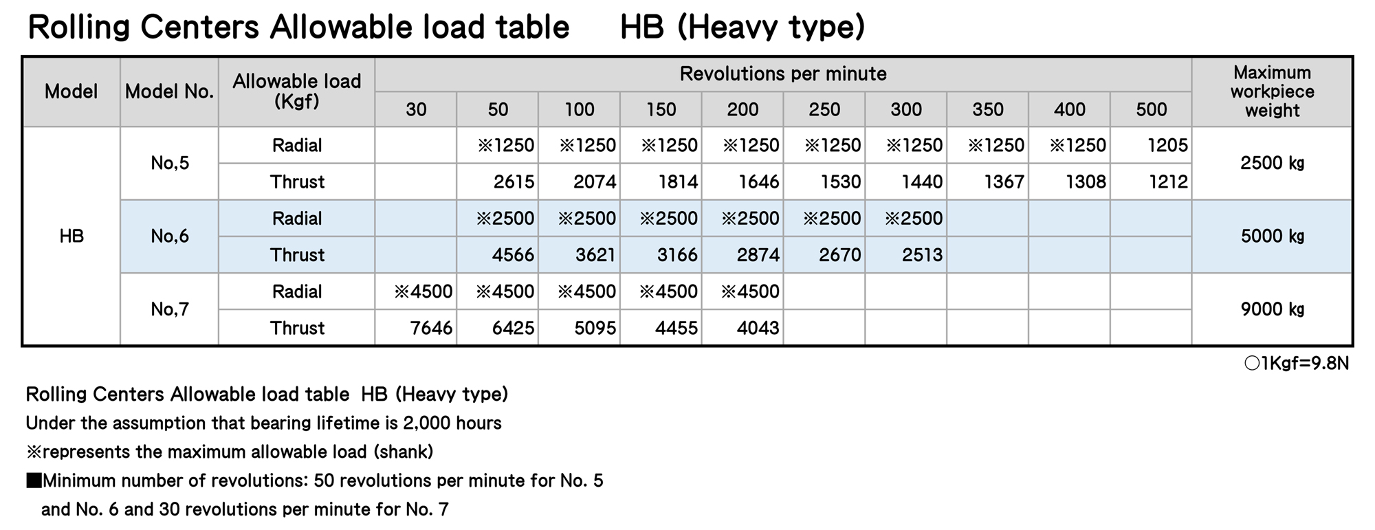
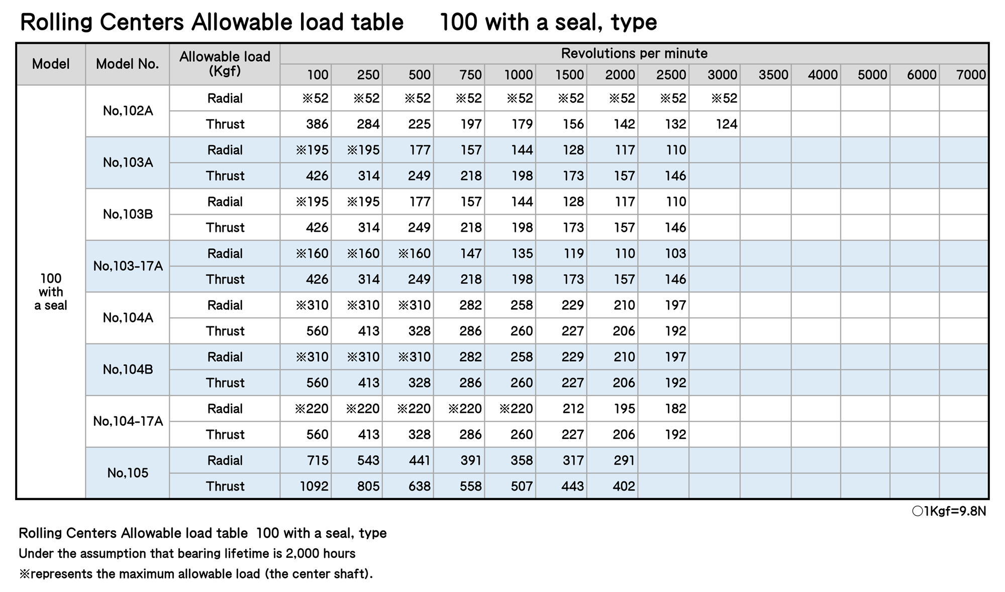
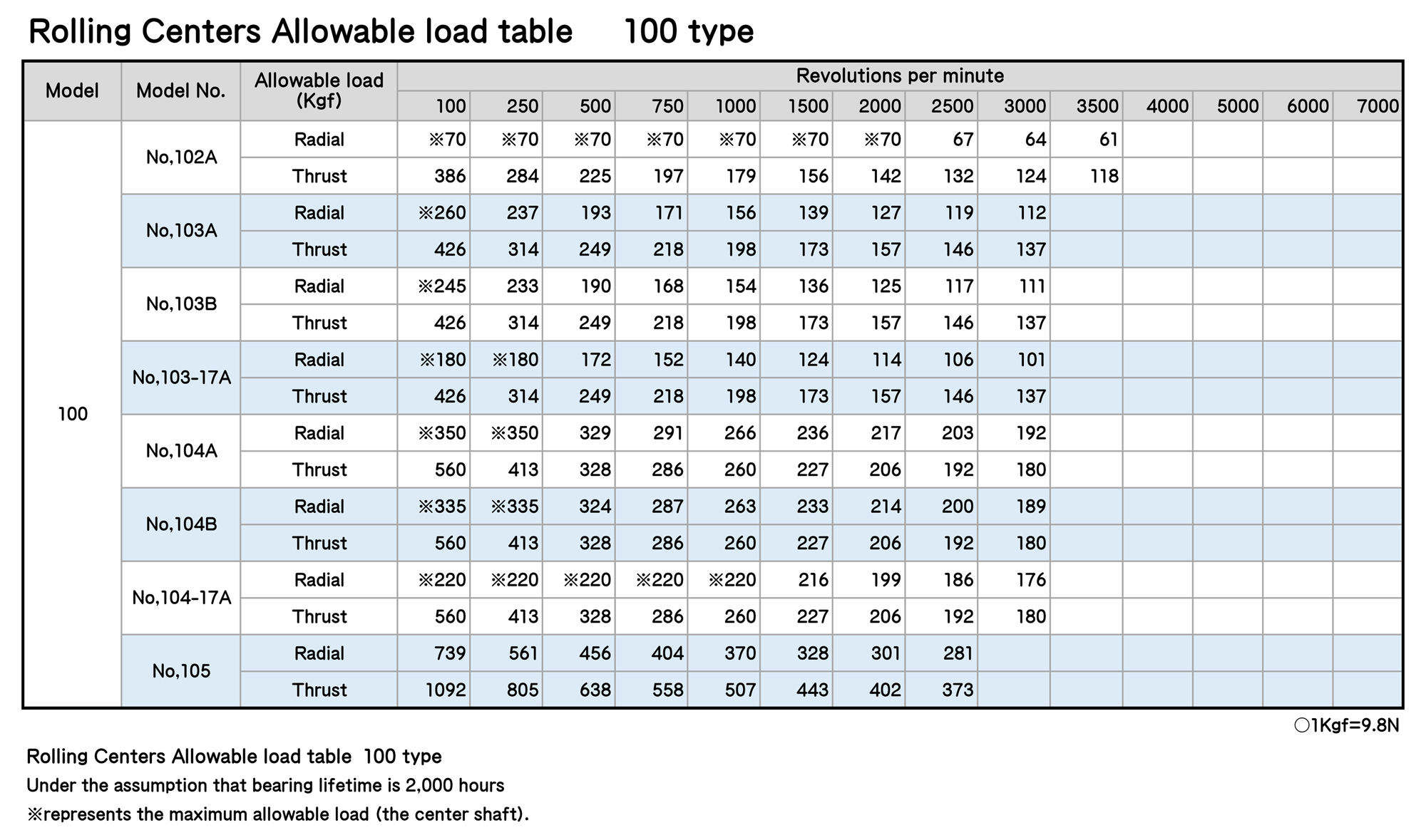
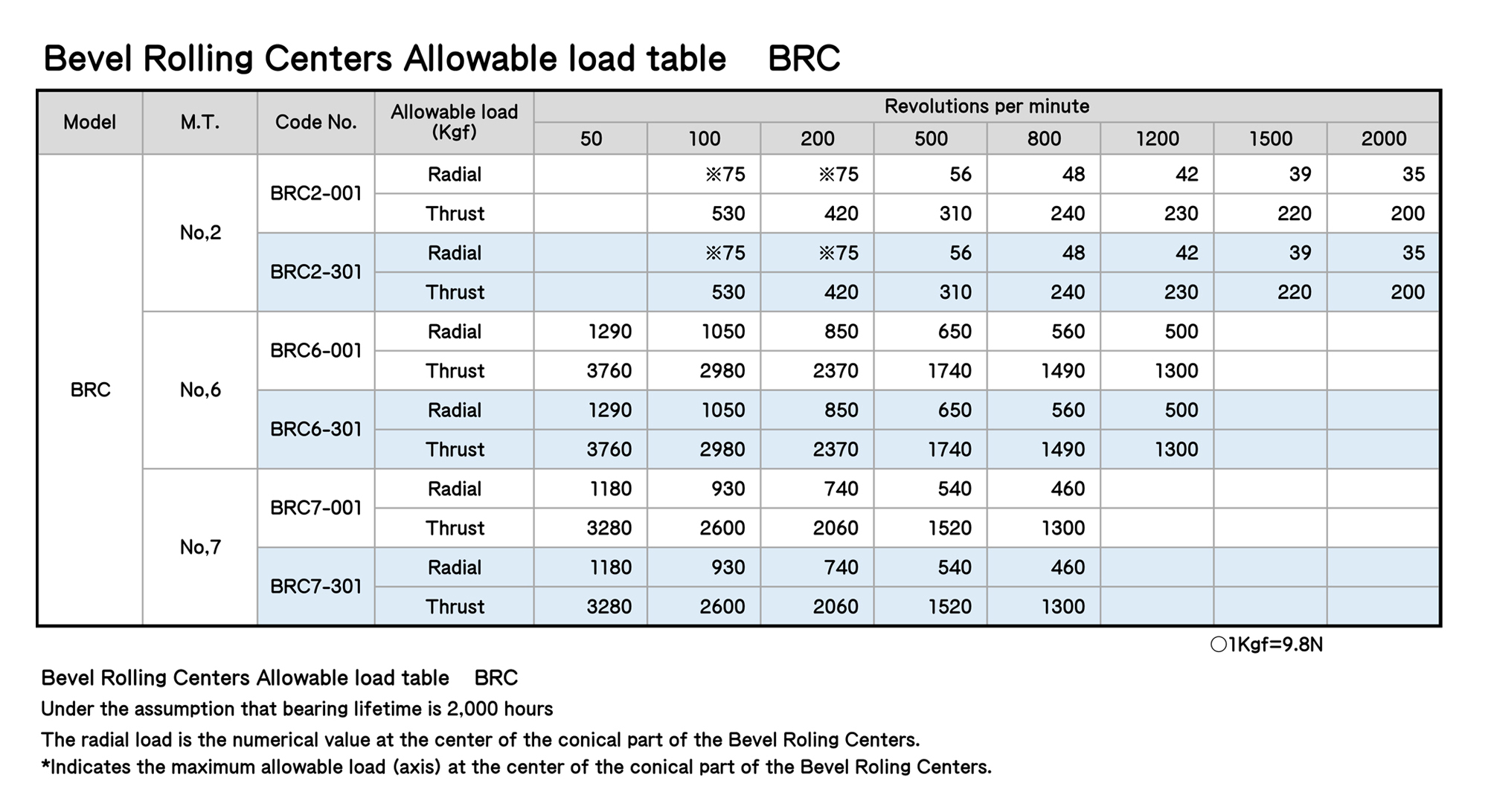
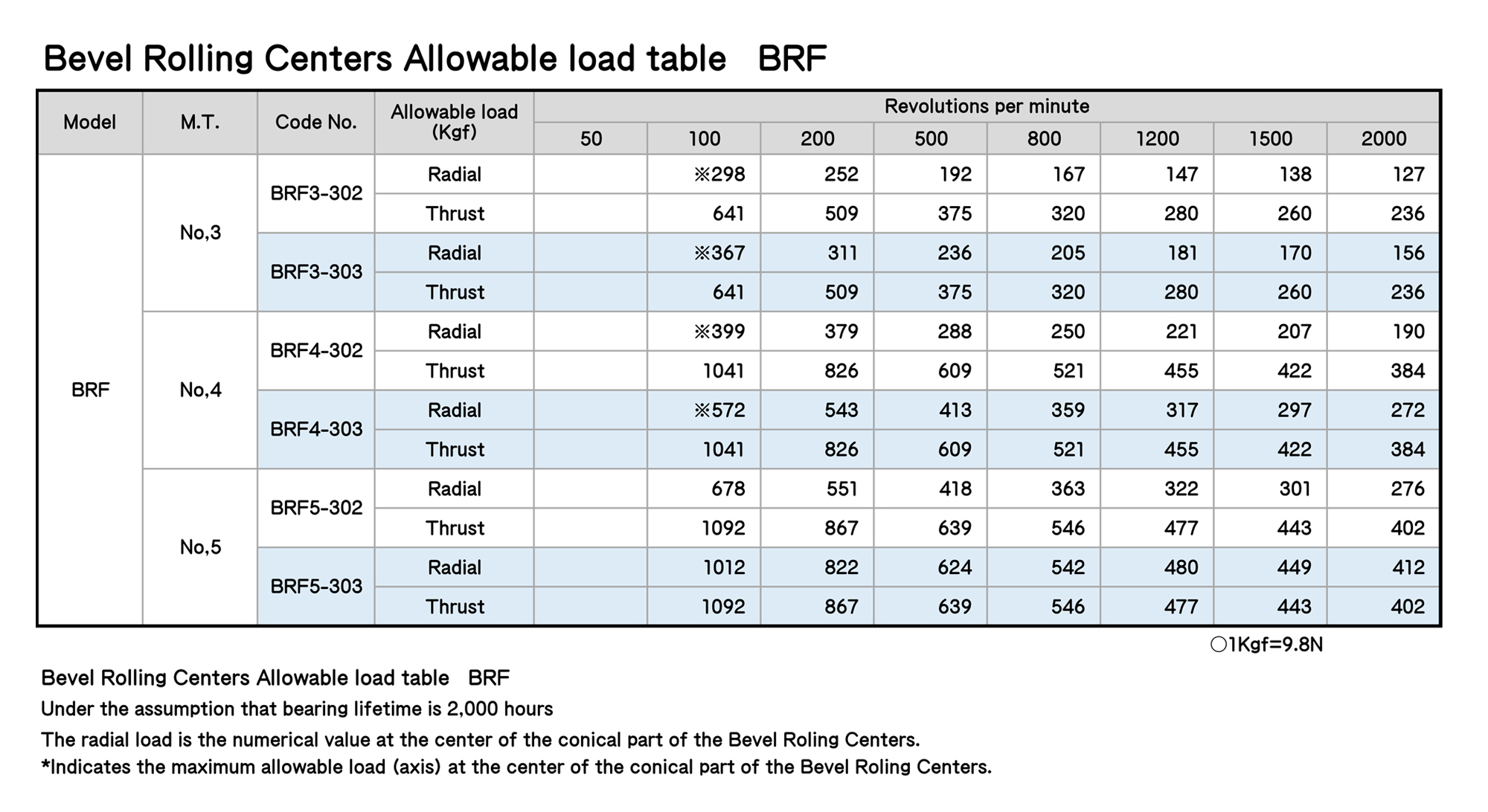
Rolling Centers Allowable load table
Under the assumption that bearing lifetime is 2,000 hours
※represents the maximum allowable load (the center shaft).
① 5,500 revolutions per minute
② 4,500 revolutions per minute
③ 3,800 revolutions per minute
ROLLING CENTERS
ROLLING CENTERS

ROLLING CENTERS
ROLLING CENTERS
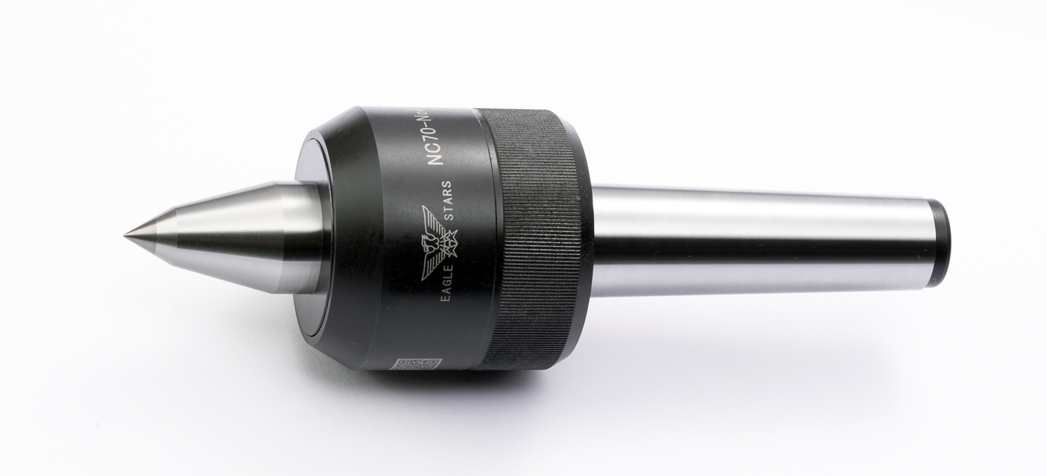
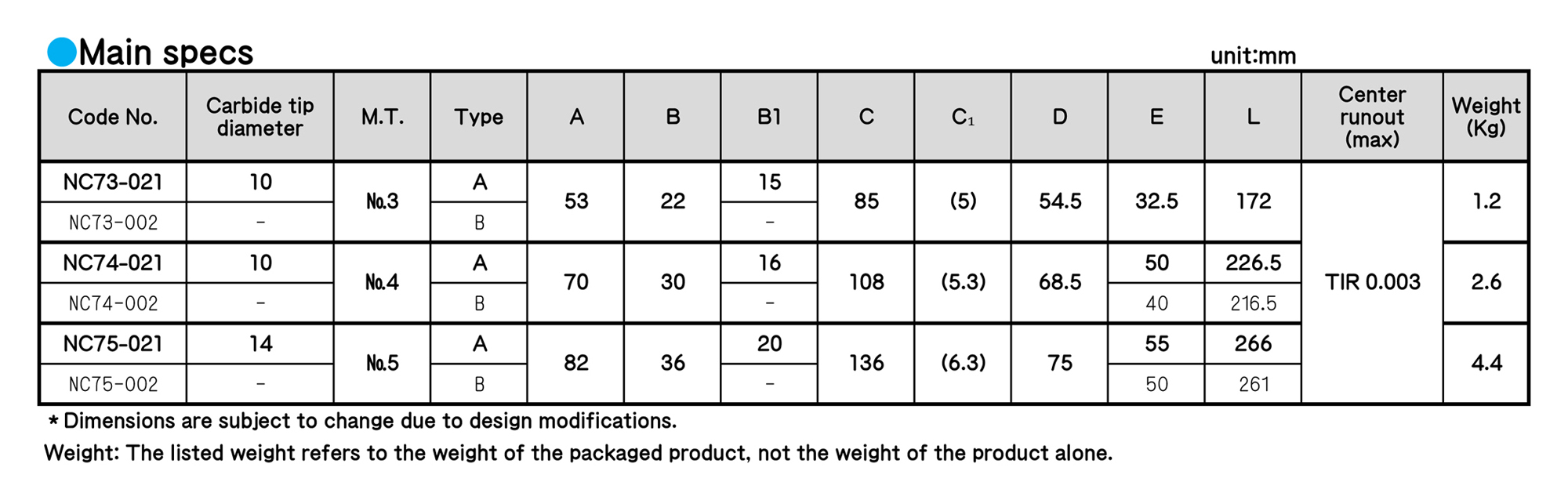
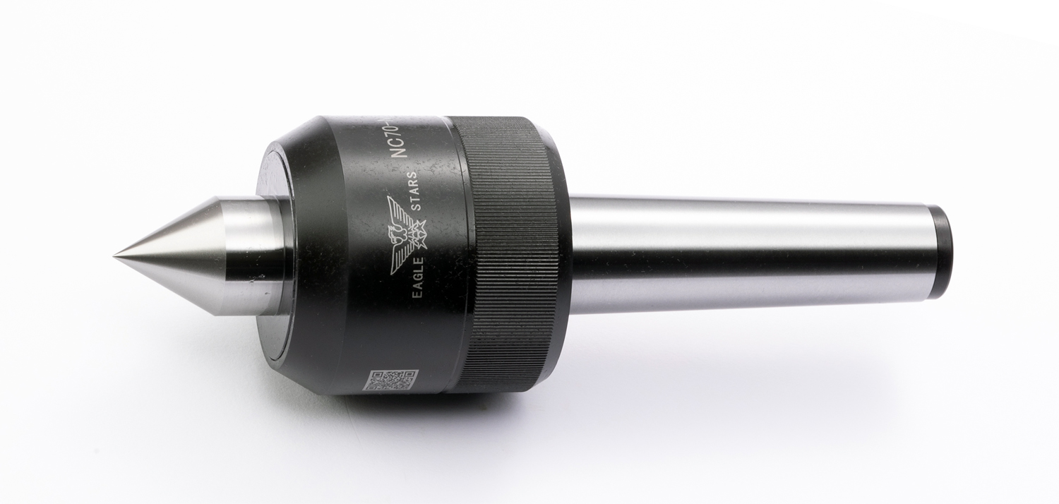
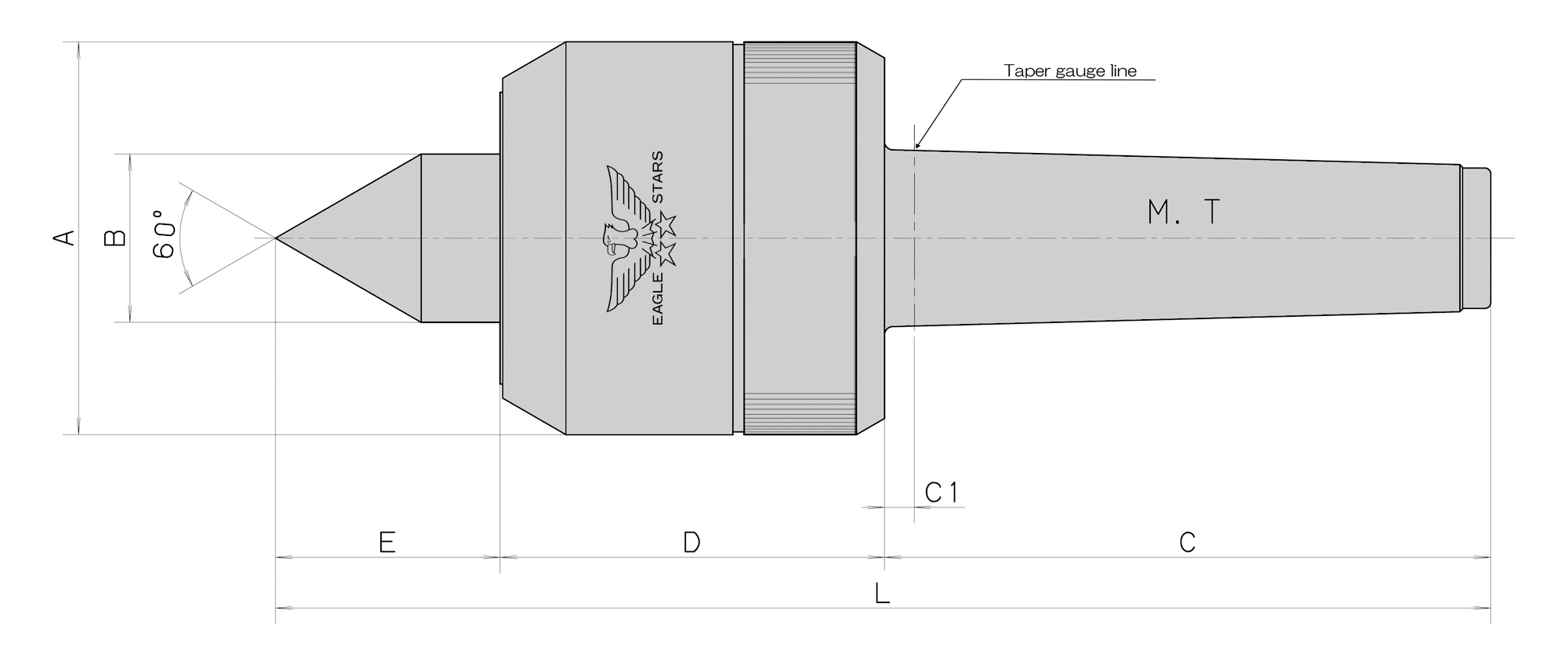
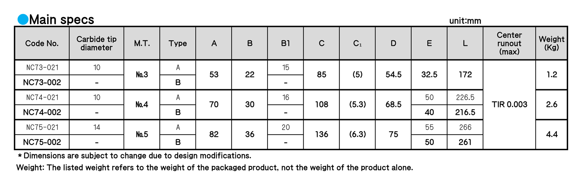
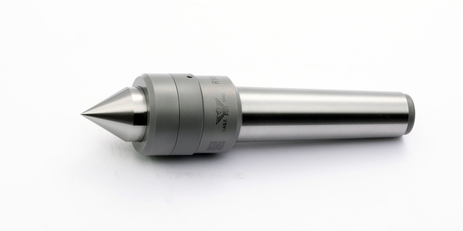
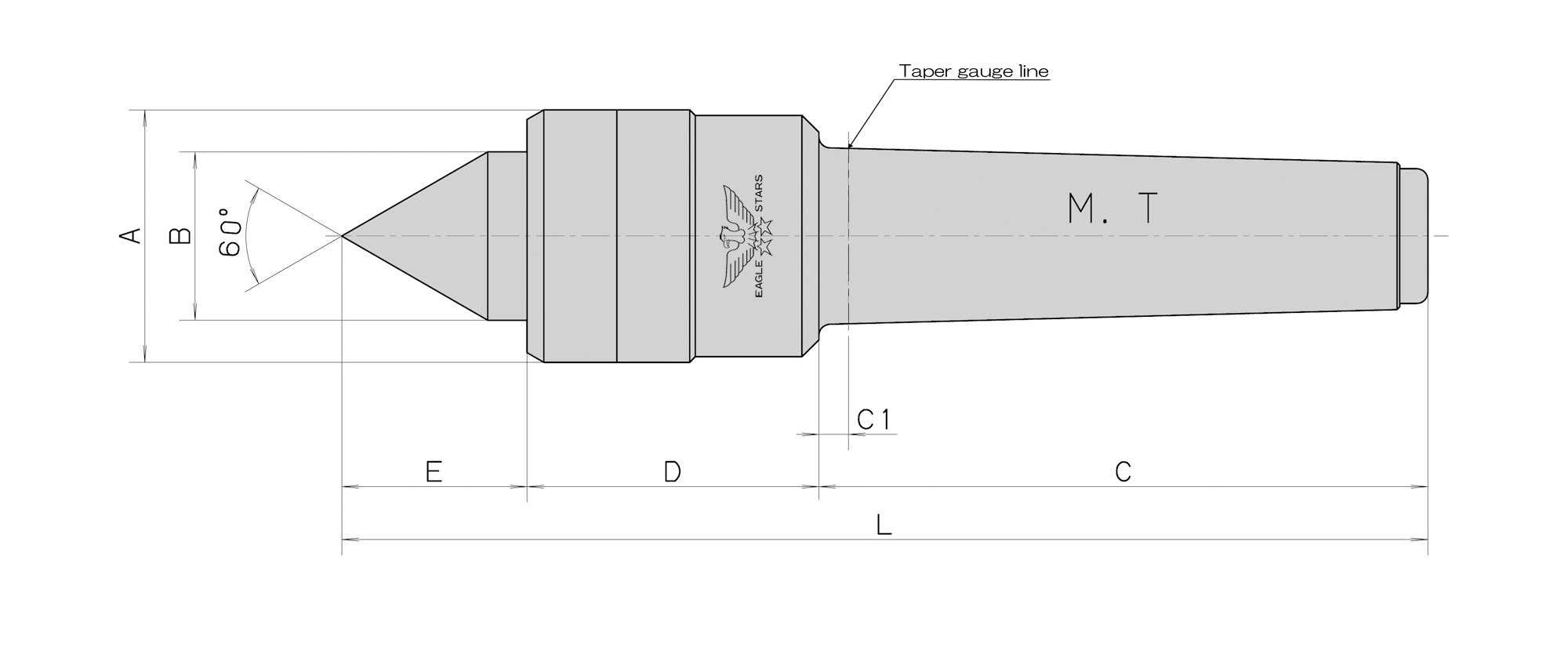
■ We design NC70 to achieve ultrahigh rotation (7.000 revolutions per minute ) and high precision (TIR:0.003)
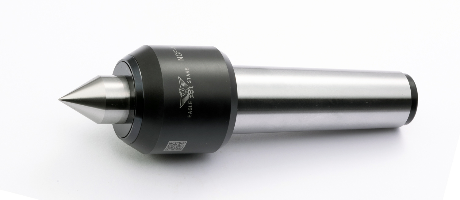
■ A carbide tip attached to the tip part can withstand abrasion and friction generated by ultra-high rotation.(Type A)
■ We incorporate three-rows angular bearings and a needle bearing inside NC70 to enhance the rigidity.
■ We adopt an original (non-contact) labyrinth mechanism to prevent the invasion of cutting oil. This labyrinth mechanism enhances the precision and extends the lifespan because this mechanism reduce abrasion, friction, power loss and avoid a rise in temperature of this machine.
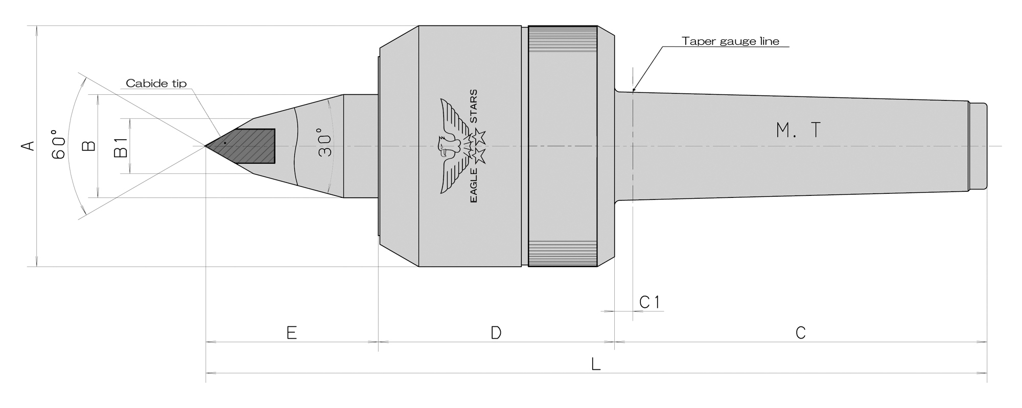
◆ The V seal is necessary if you use NC70 for a grinding machine or use NC70 at the rotation speed 1000 min-1 or less. As necessary, please contact us.
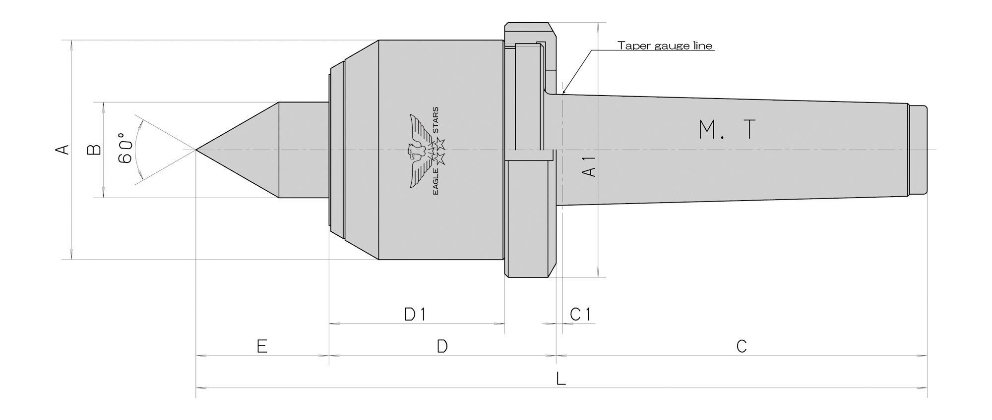
◆ For some grinding machines, the standard taper position is deep inside the taper hole. In this case, the special specs with C1 being longer need to be applied.
Please contact us, and we will estimate the turnaround time and price for the product based on a route you have specified.
ROLLING CENTERS
■ We design NC70 to achieve ultrahigh rotation (7.000 revolutions per minute ) and high precision (TIR:0.003)
■ A carbide tip attached to the tip part can withstand abrasion and friction generated by ultra-high rotation.(Type A)
■ We incorporate three-rows angular bearings and a needle bearing inside NC70 to enhance the rigidity.
■ We adopt an original (non-contact) labyrinth mechanism to prevent the invasion of cutting oil. This labyrinth mechanism enhances the precision and extends the lifespan because this mechanism reduce abrasion, friction, power loss and avoid a rise in temperature of this machine.
◆ The V seal is necessary if you use NC70 for a grinding machine or use NC70 at the rotation speed 1000 min-1 or less. As necessary, please contact us.
◆ For some grinding machines, the standard taper position is deep inside the taper hole. In this case, the special specs with C1 being longer need to be applied.
Please contact us, and we will estimate the turnaround time and price for the product based on a route you have specified.
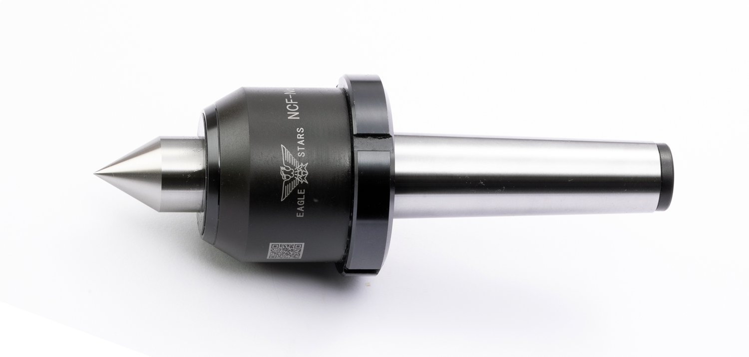
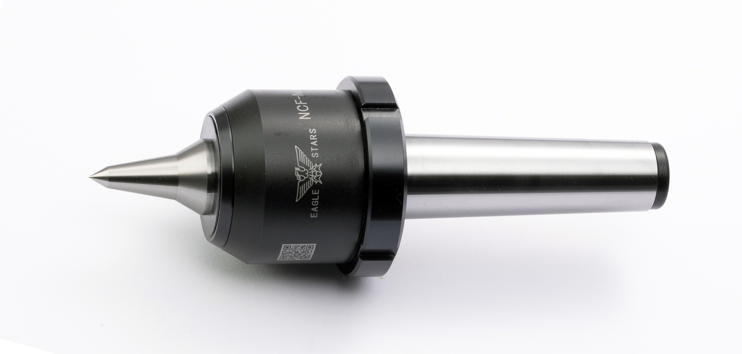
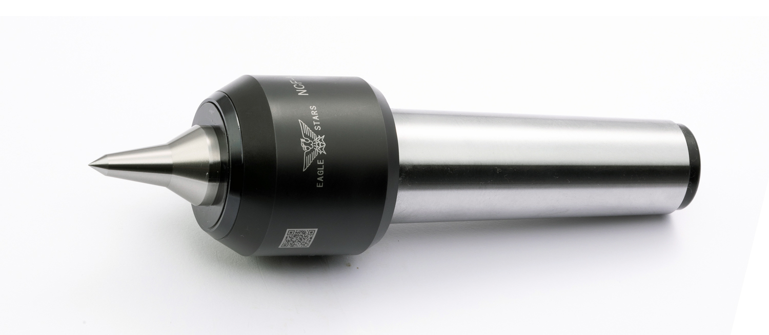
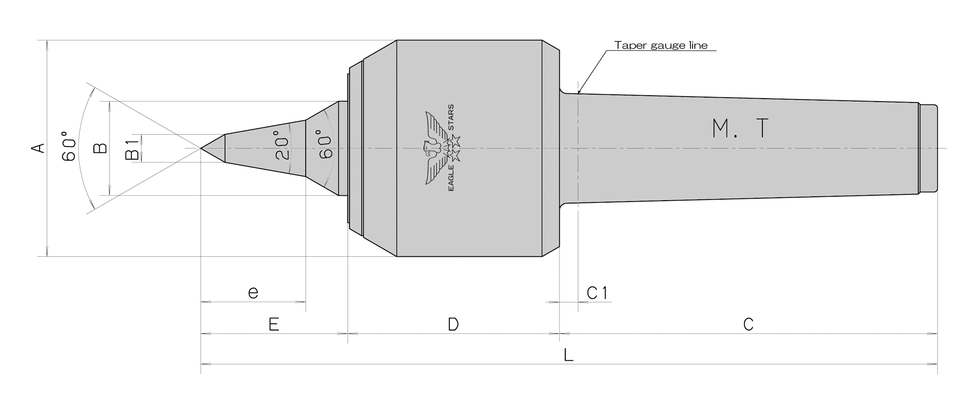
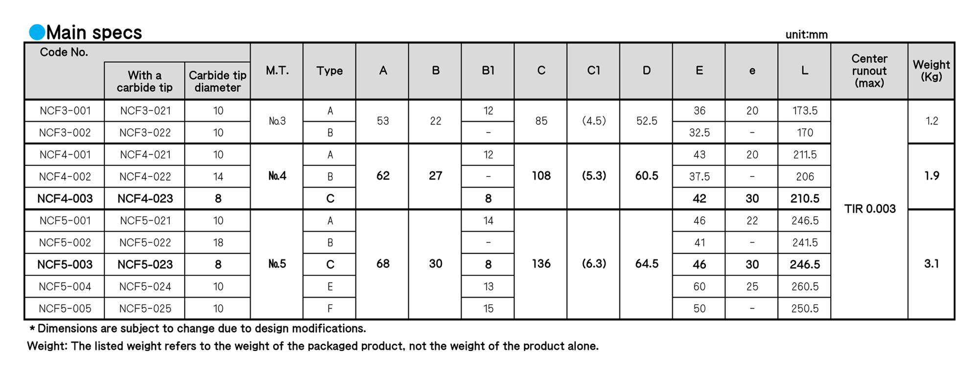
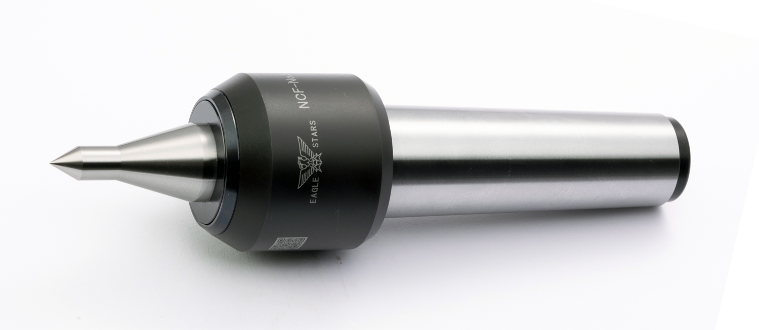
ROLLING CENTERS
ROLLING CENTERS
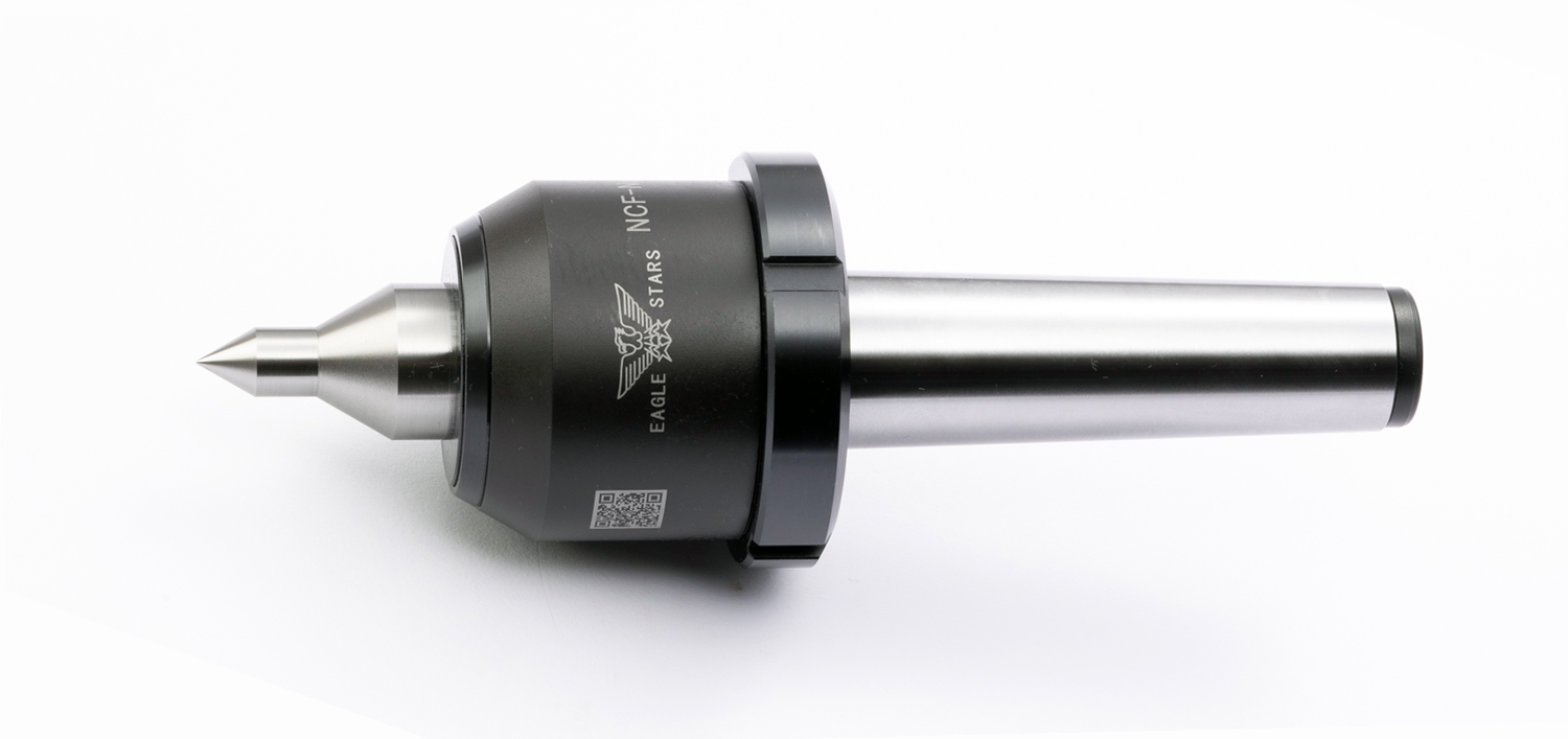
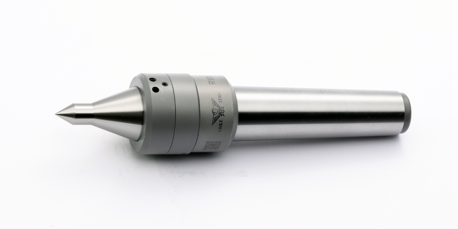
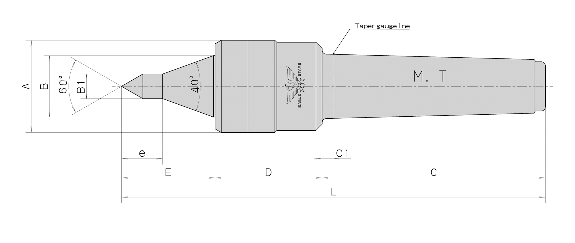
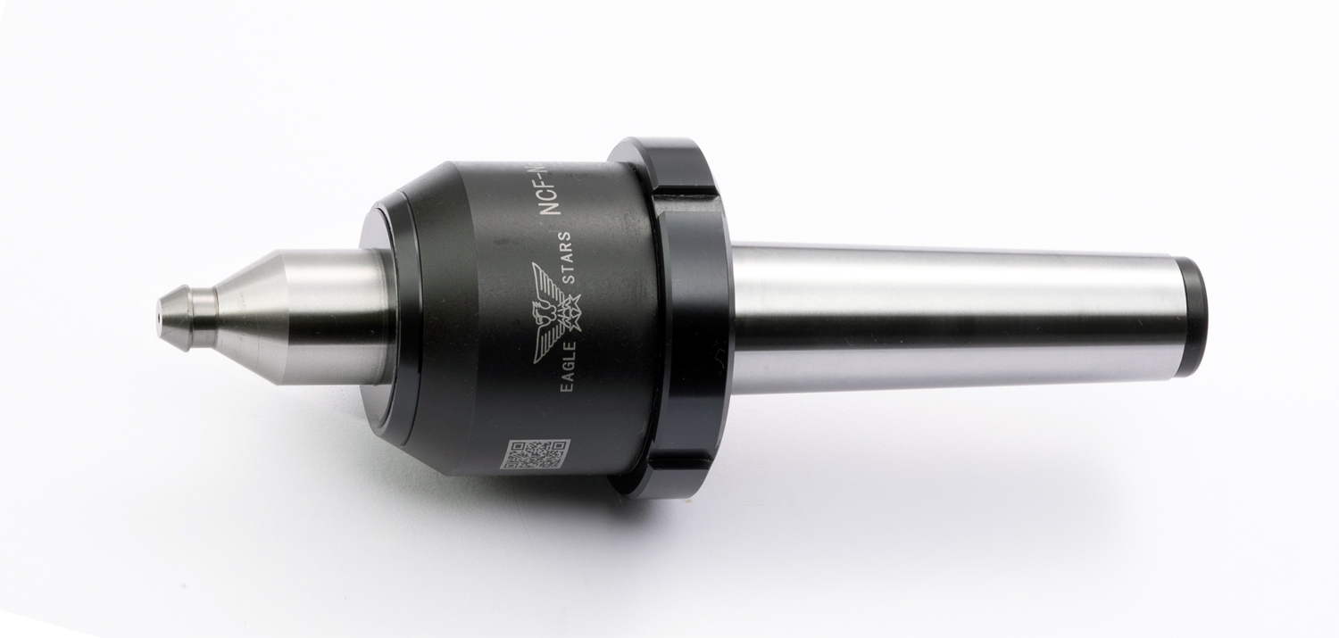
■Maximum rotation rate: 5,500 revolutions per minute
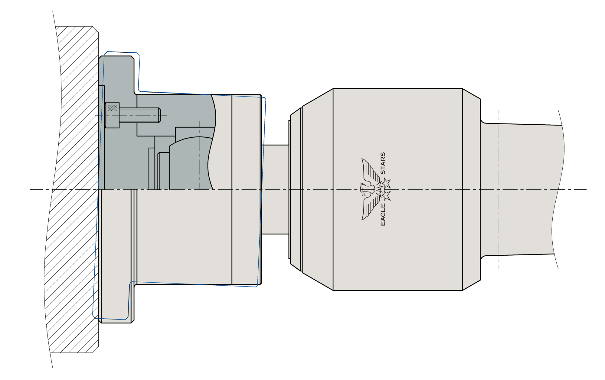
■ A detaching nut attached to the rear part of the body enables this product to remove from the front part of the tailstock.
■ We incorporate three rows angular bearings and a needle bearing Inside NCF-N to make the rotaly torque smooth.
■ Types A and C are thin types, and suited for thread cutting and end face processing.
■ We adopt a (non-contact) labyrinth mechanism, to prevent the invasion of cutting oil.
■ We recommend you use NCF-N and our work-driving center because we desing NCF-N to tolerate thrust load.
◆The V seal is necessary if you use NCF-N for a grinding machine or use NCF-N at the rotation speed 1000 min-1 or less.As necessary, please contact us.
◆ For some grinding machines, the standard taper position is deep inside the taper hole. In this case, the special specs with C1 being longer need to be applied.
◆ Please contact us, and we will estimate the turnaround time and price for the product based on a route you have specified.
Regarding use
■ If there is no load onto the center shaft, the center shaft moves up to 0.5 mm. Please apply thrust at the time of use.
ROLLING CENTERS
■Maximum rotation rate: 5,500 revolutions per minute
■ A detaching nut attached to the rear part of the body enables this product to remove from the front part of the tailstock.
■ We incorporate three rows angular bearings and a needle bearing Inside NCF-N to make the rotaly torque smooth.
■ Types A and C are thin types, and suited for thread cutting and end face processing.
■ We adopt a (non-contact) labyrinth mechanism, to prevent the invasion of cutting oil.
■ We recommend you use NCF-N and our work-driving center because we desing NCF-N to tolerate thrust load.
◆The V seal is necessary if you use NCF-N for a grinding machine or use NCF-N at the rotation speed 1000 min-1 or less.As necessary, please contact us.
◆ For some grinding machines, the standard taper position is deep inside the taper hole. In this case, the special specs with C1 being longer need to be applied.
◆ Please contact us, and we will estimate the turnaround time and price for the product based on a route you have specified.
Regarding use
■ If there is no load onto the center shaft, the center shaft moves up to 0.5 mm. Please apply thrust at the time of use.
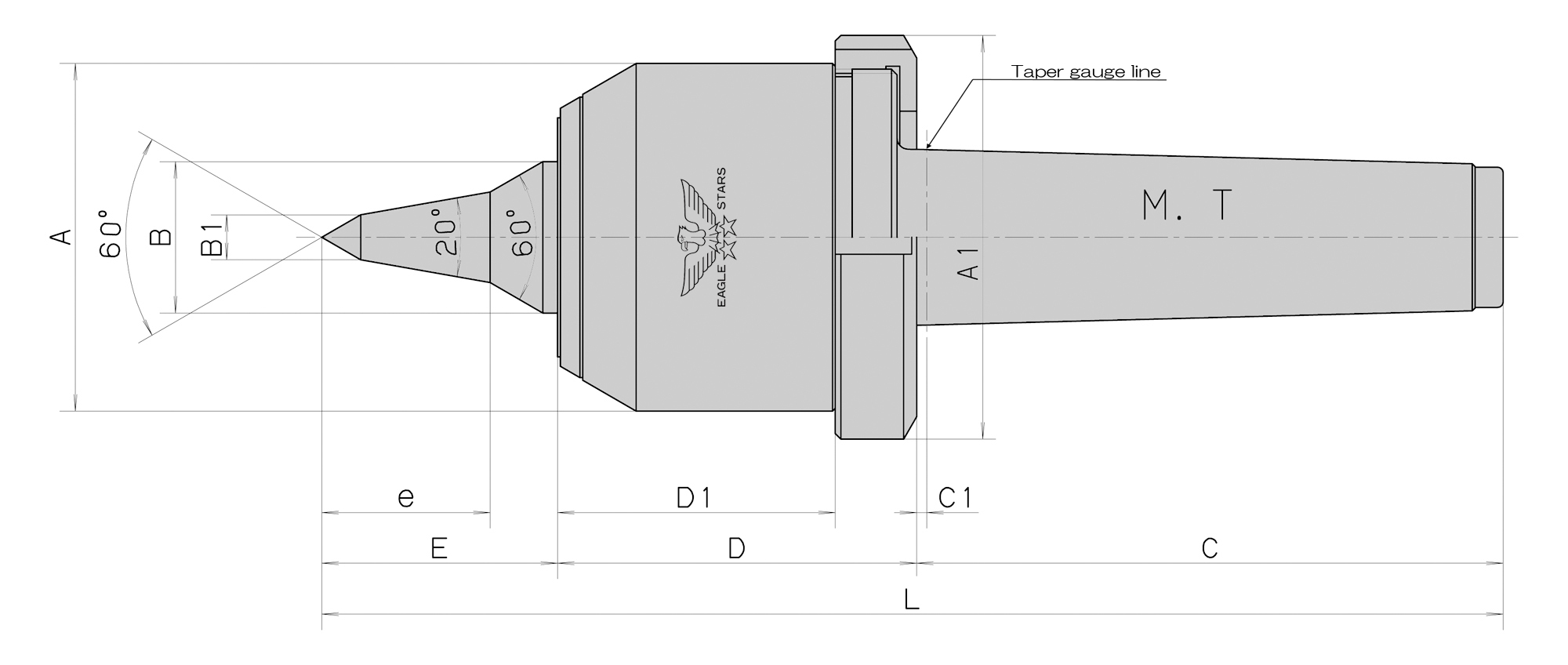
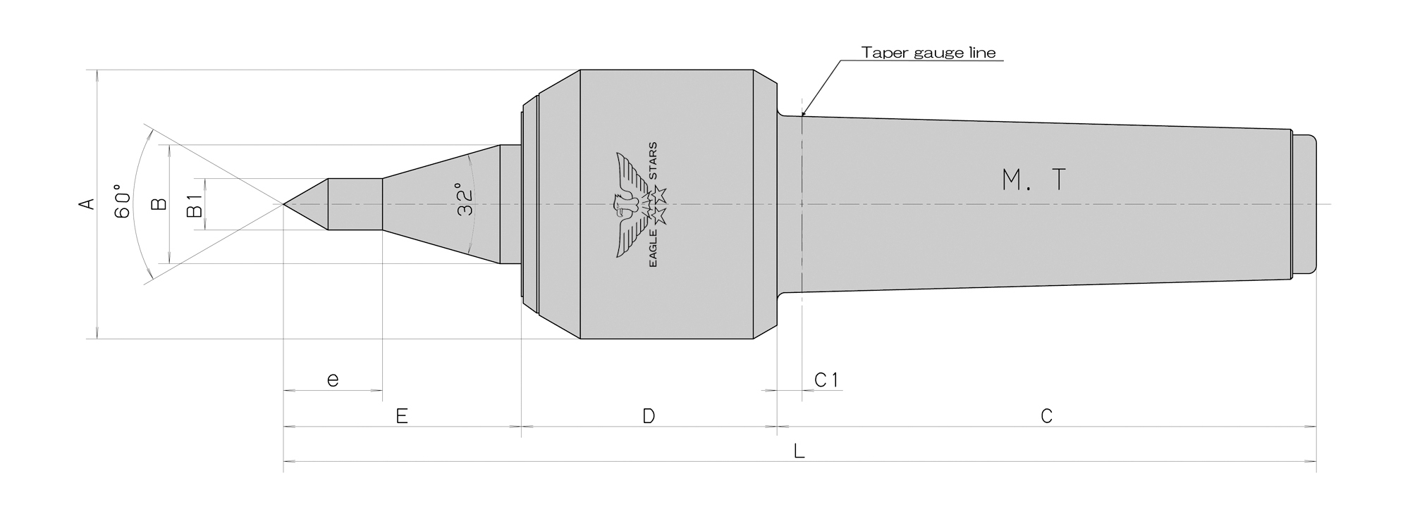
ROLLING CENTERS
ROLLING CENTERS
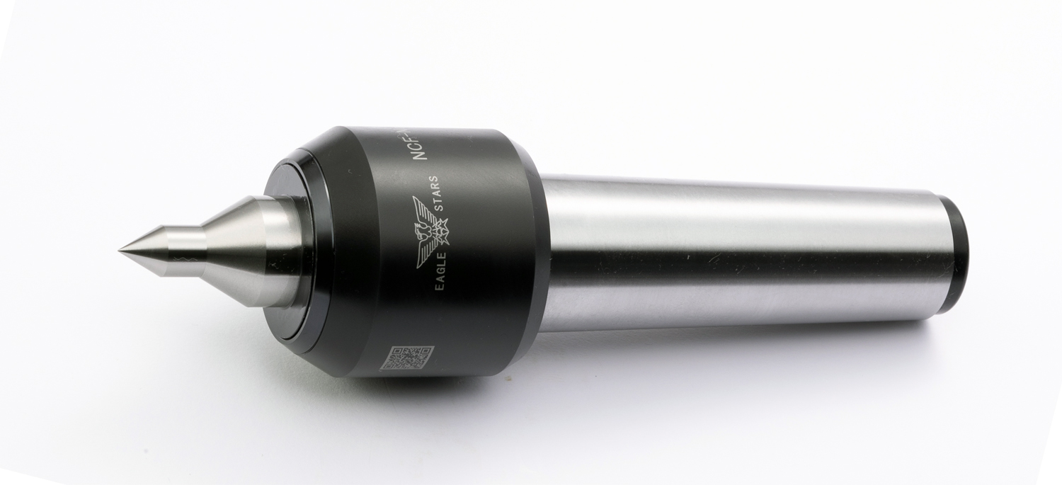

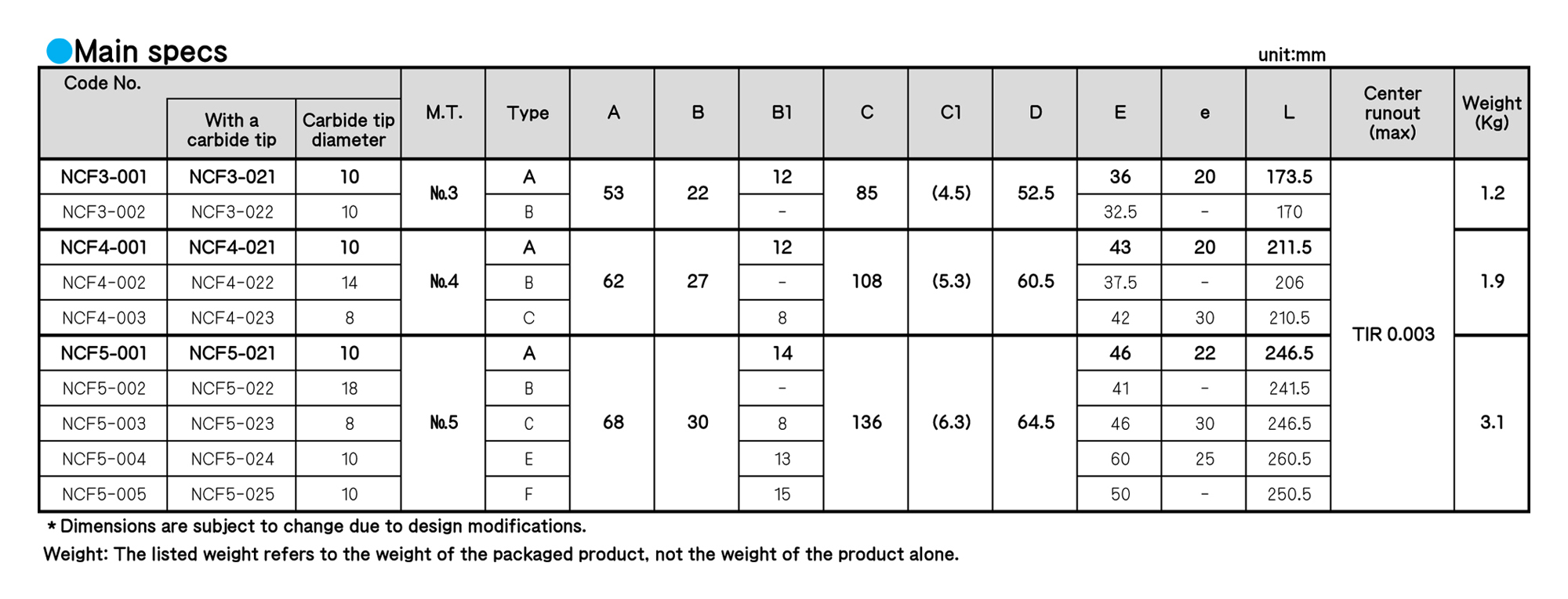
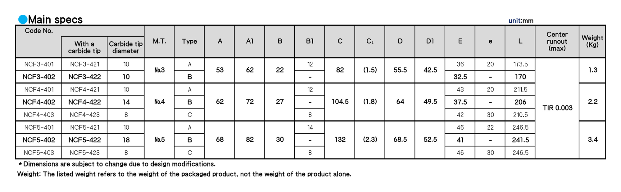
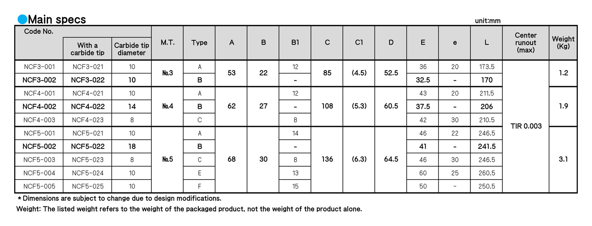
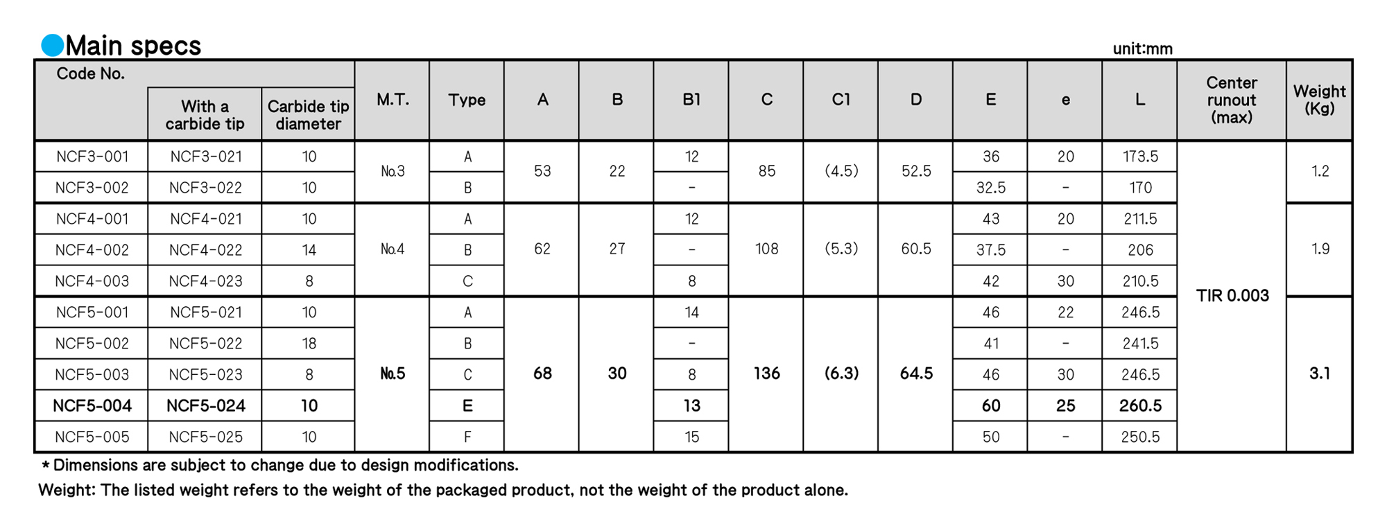
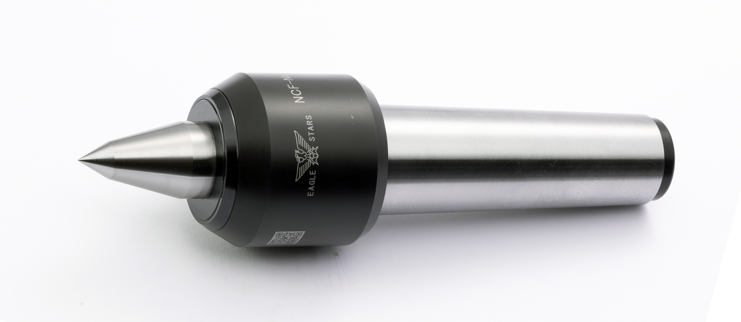
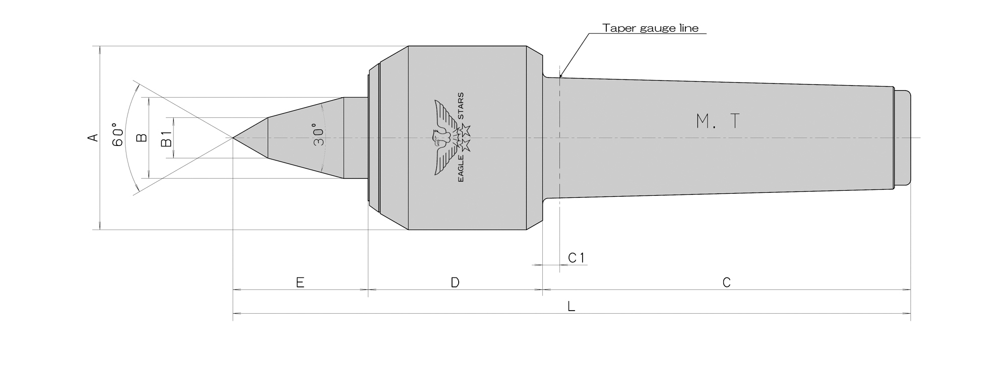
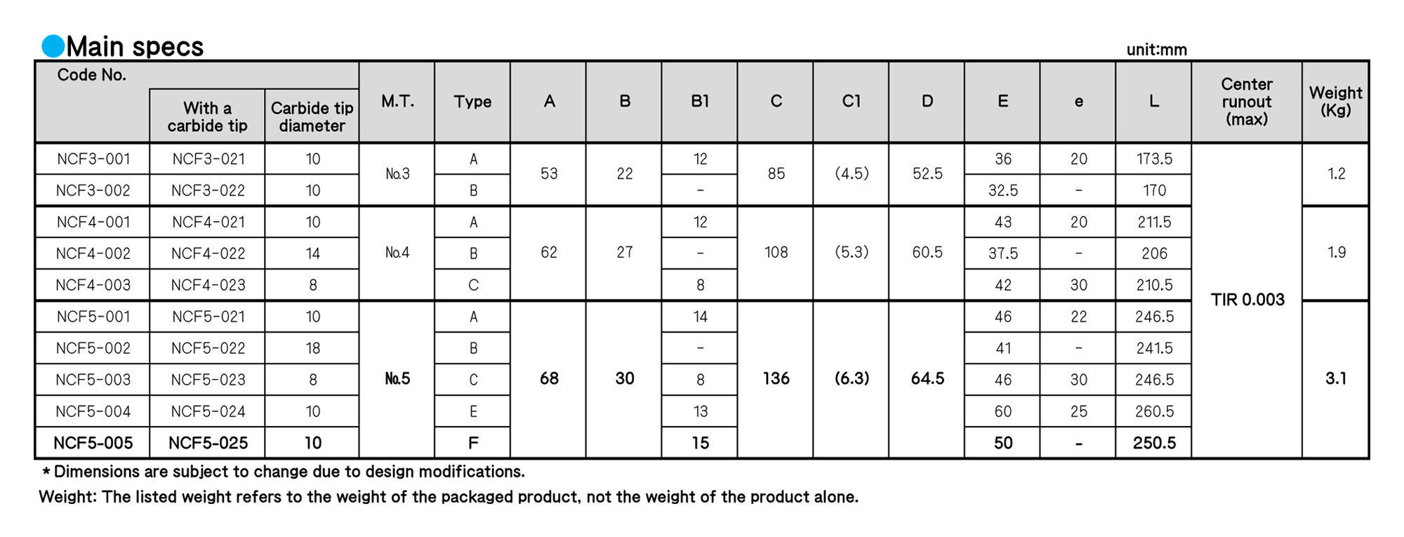
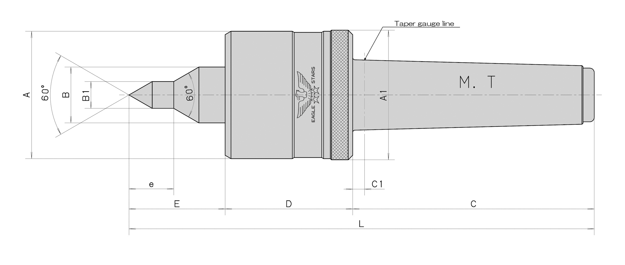
■ Maximum rotation rate is 4,500 revolutions per minute for No. 3, 4,000 revolutions per minute for No. 4 and 3,800 revolutions per minute for No. 5.
■ We incorporate two-rows of angular bearings, a thrust bearings and a needle bearing inside NCF to make the rotary torque smooth.
■ Types A, C and E are thin types, and suited for thread cutting and end face processing.
■We adopt a(non-contact)labyrinth mechanism to prevent the invasion of cutting oil.
◆The V seal is necessary if you use NCF for a grinding machine or use NCF at the rotation speed 1000 min-1 or less.As necessary, please contact us.
◆ For some grinding machines, the standard taper position is deep inside the taper hole. In this case, the special specs with C1 being longer need to be applied.Please contact us, and we will estimate the turnaround time and price for the product based on a route you have specified.
ROLLING CENTERS
■ Maximum rotation rate is 4,500 revolutions per minute for No. 3, 4,000 revolutions per minute for No. 4 and 3,800 revolutions per minute for No. 5.
■ We incorporate two-rows of angular bearings, a thrust bearings and a needle bearing inside NCF to make the rotary torque smooth.
■ Types A, C and E are thin types, and suited for thread cutting and end face processing.
■We adopt a(non-contact)labyrinth mechanism to prevent the invasion of cutting oil.
◆The V seal is necessary if you use NCF for a grinding machine or use NCF at the rotation speed 1000 min-1 or less.As necessary, please contact us.
◆ For some grinding machines, the standard taper position is deep inside the taper hole. In this case, the special specs with C1 being longer need to be applied.Please contact us, and we will estimate the turnaround time and price for the product based on a route you have specified.
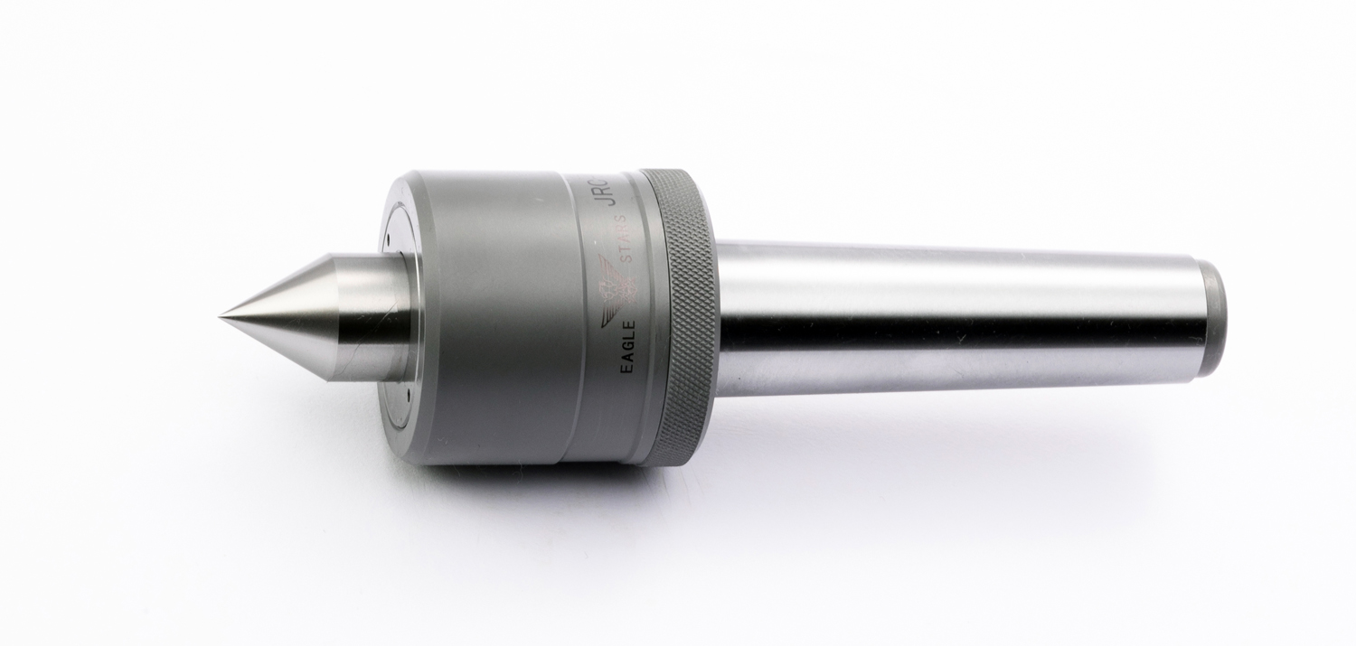
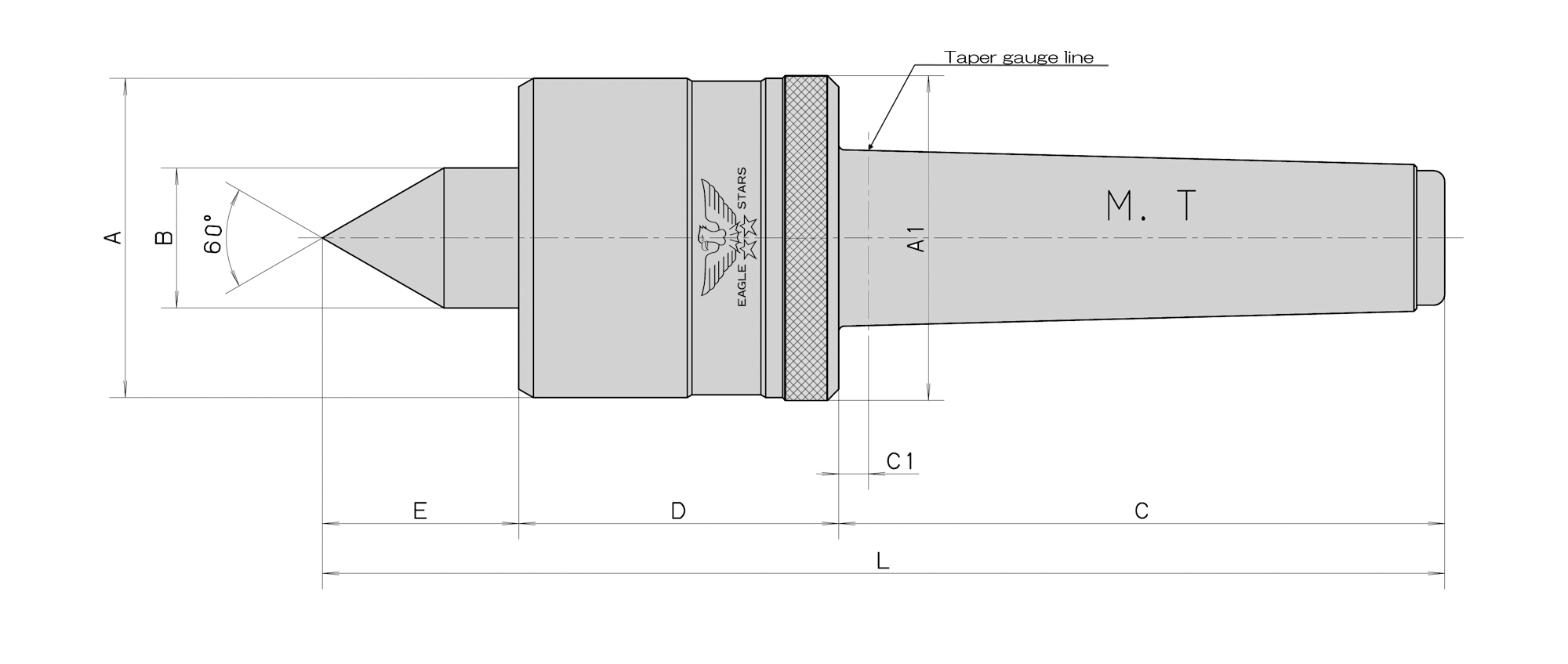
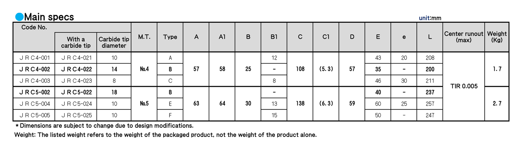
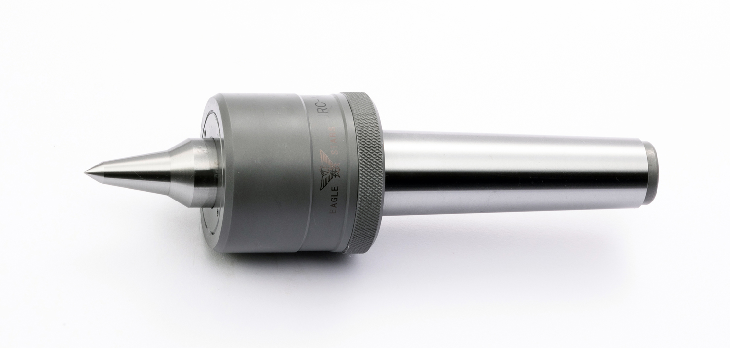
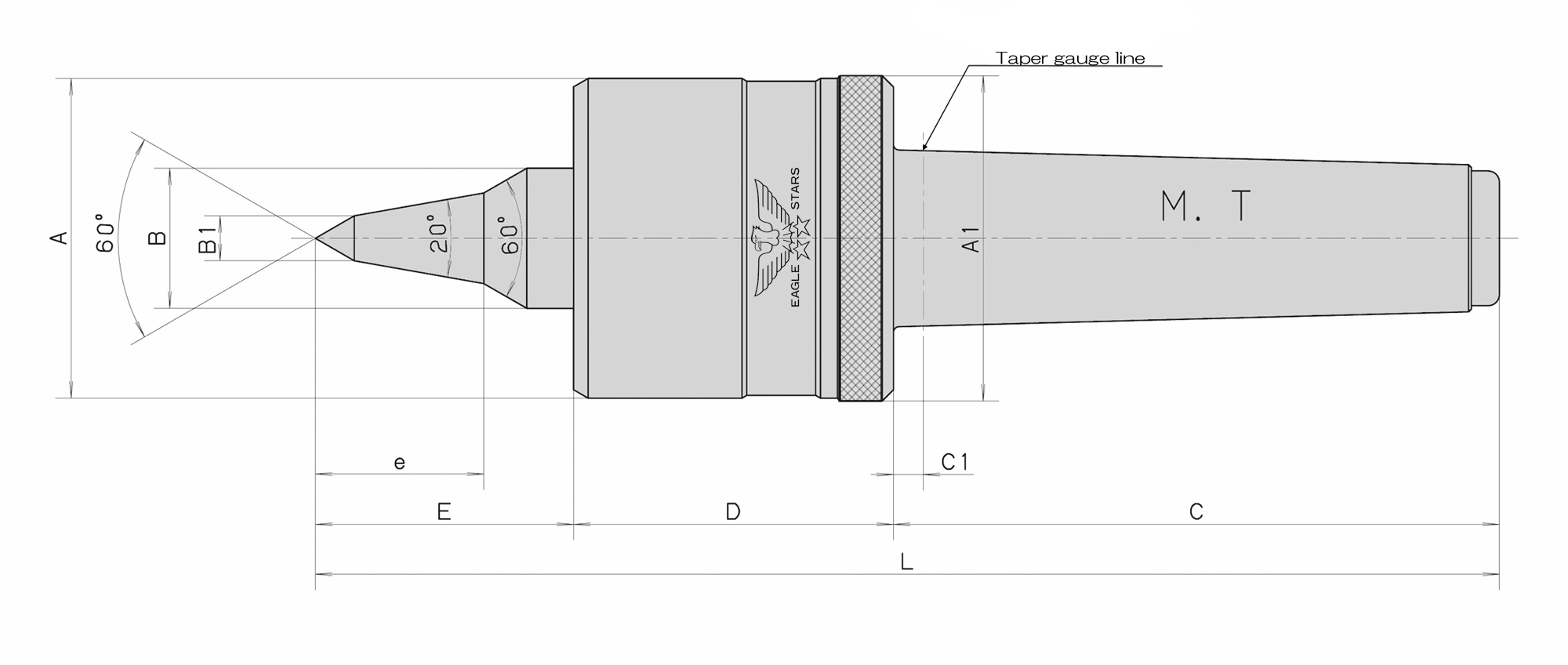
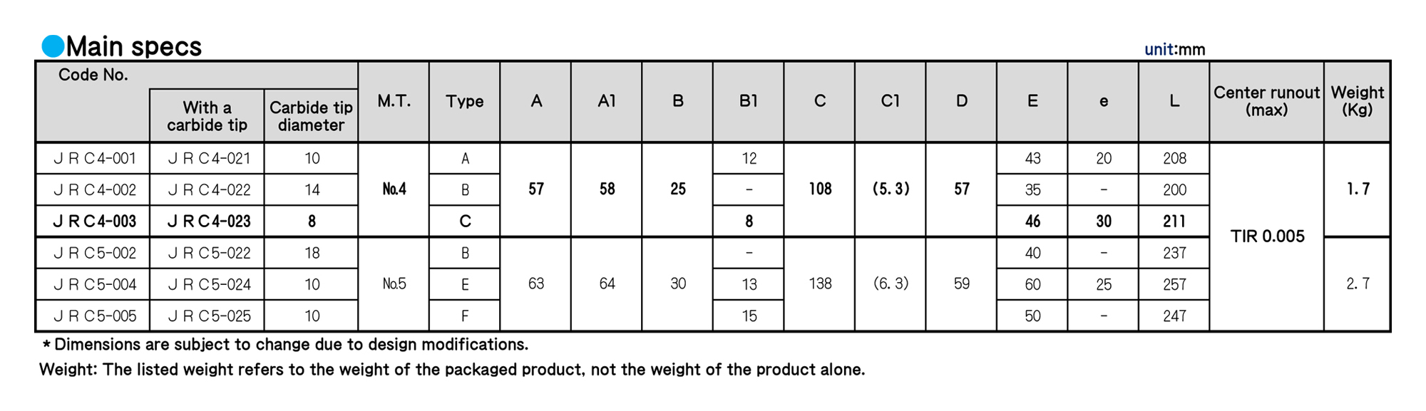
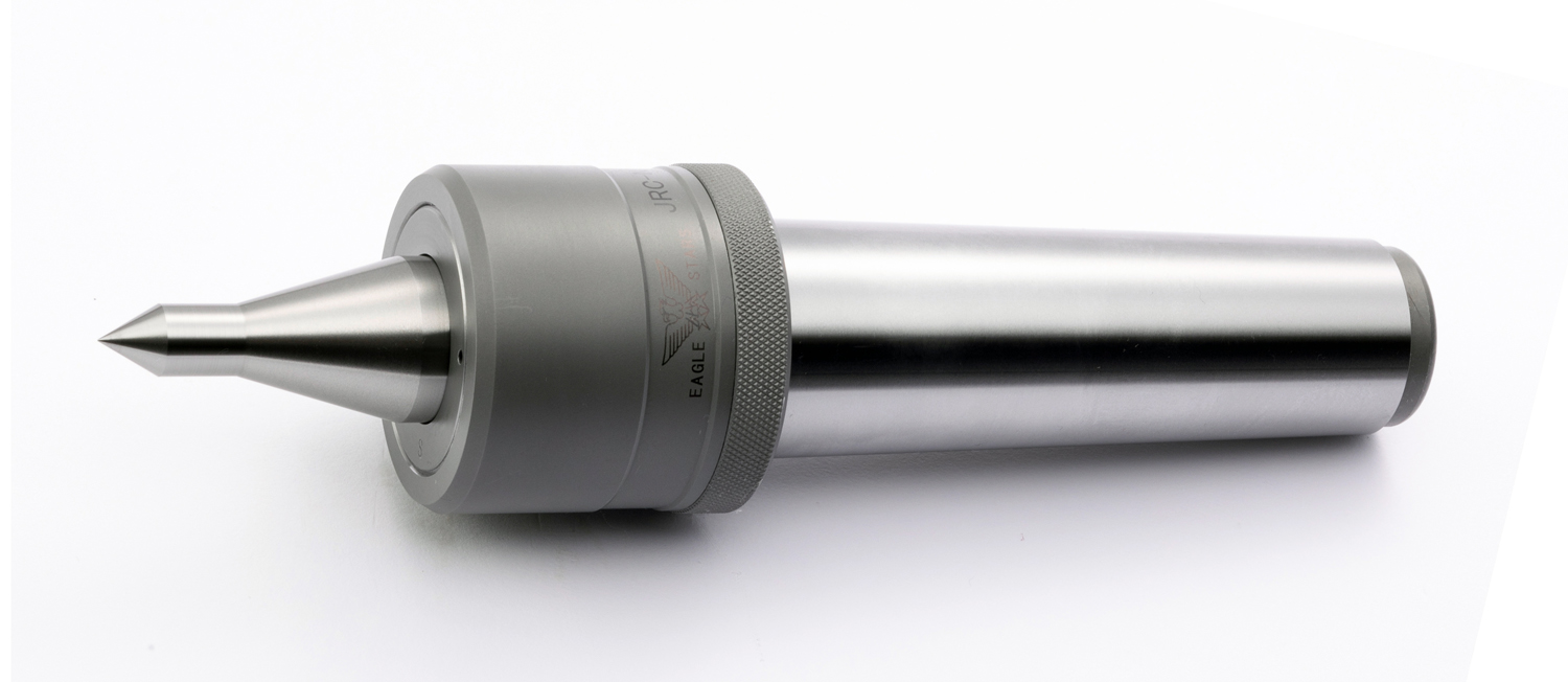
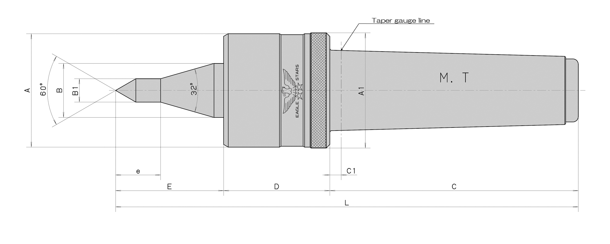
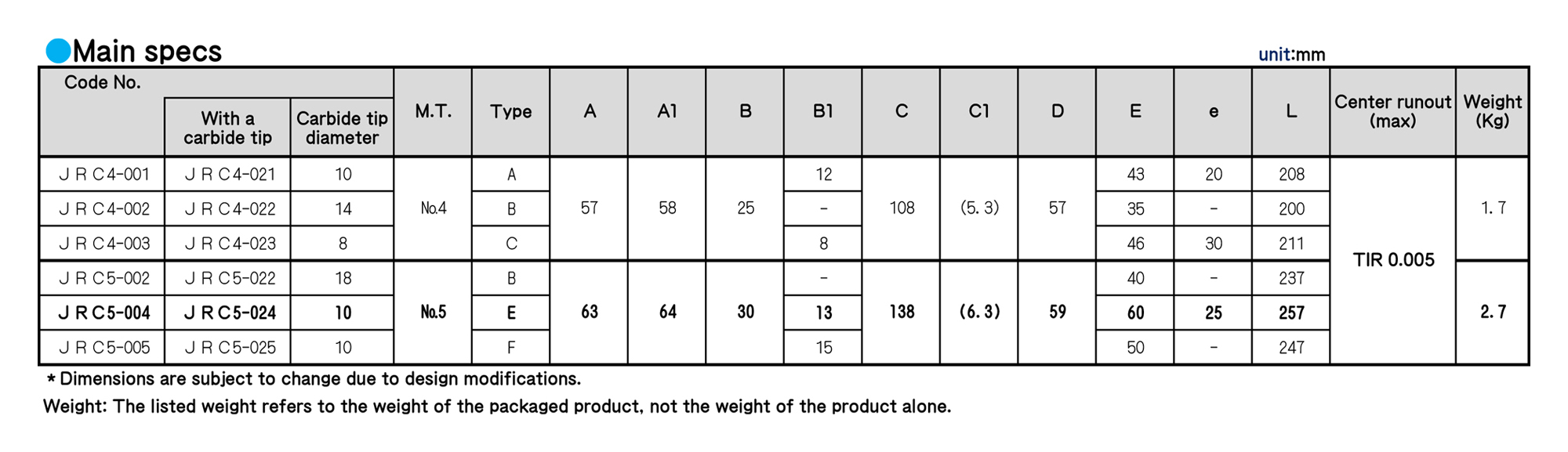
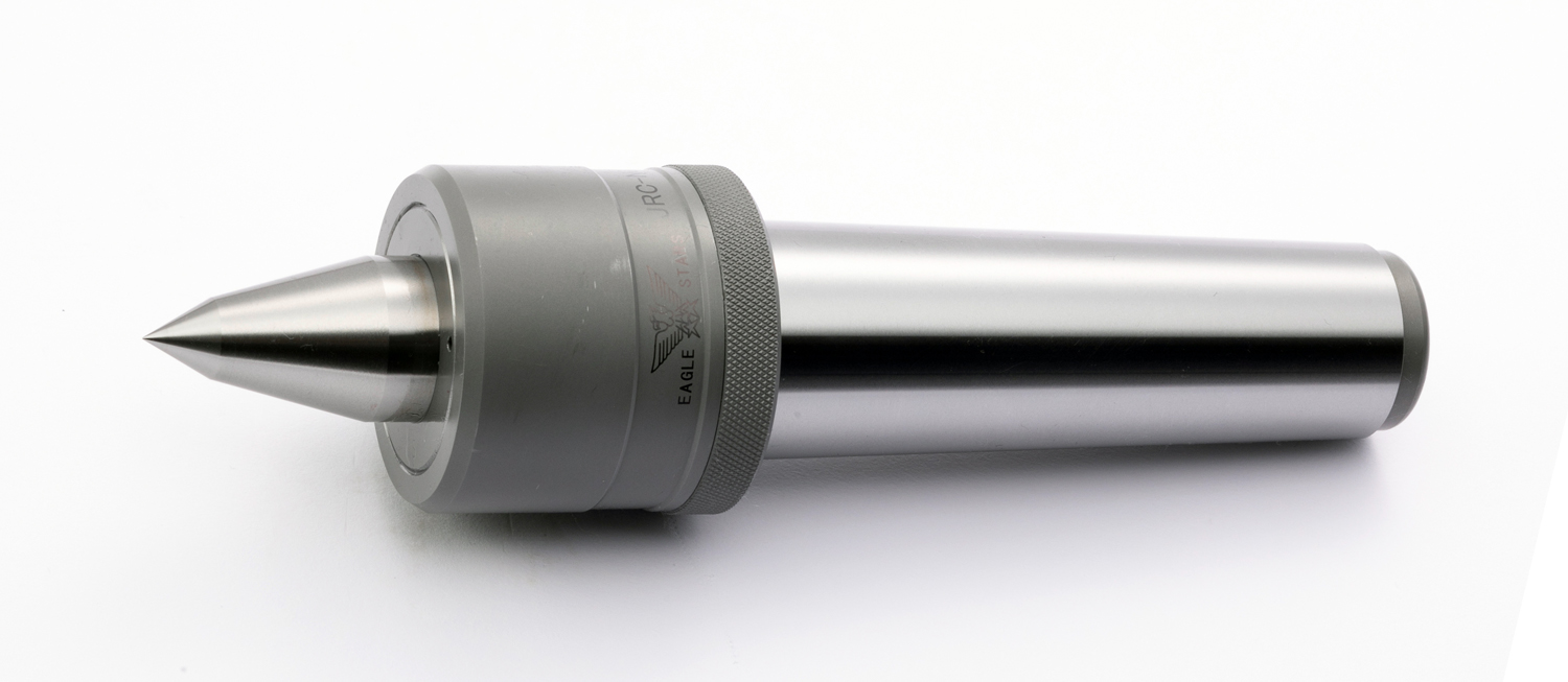
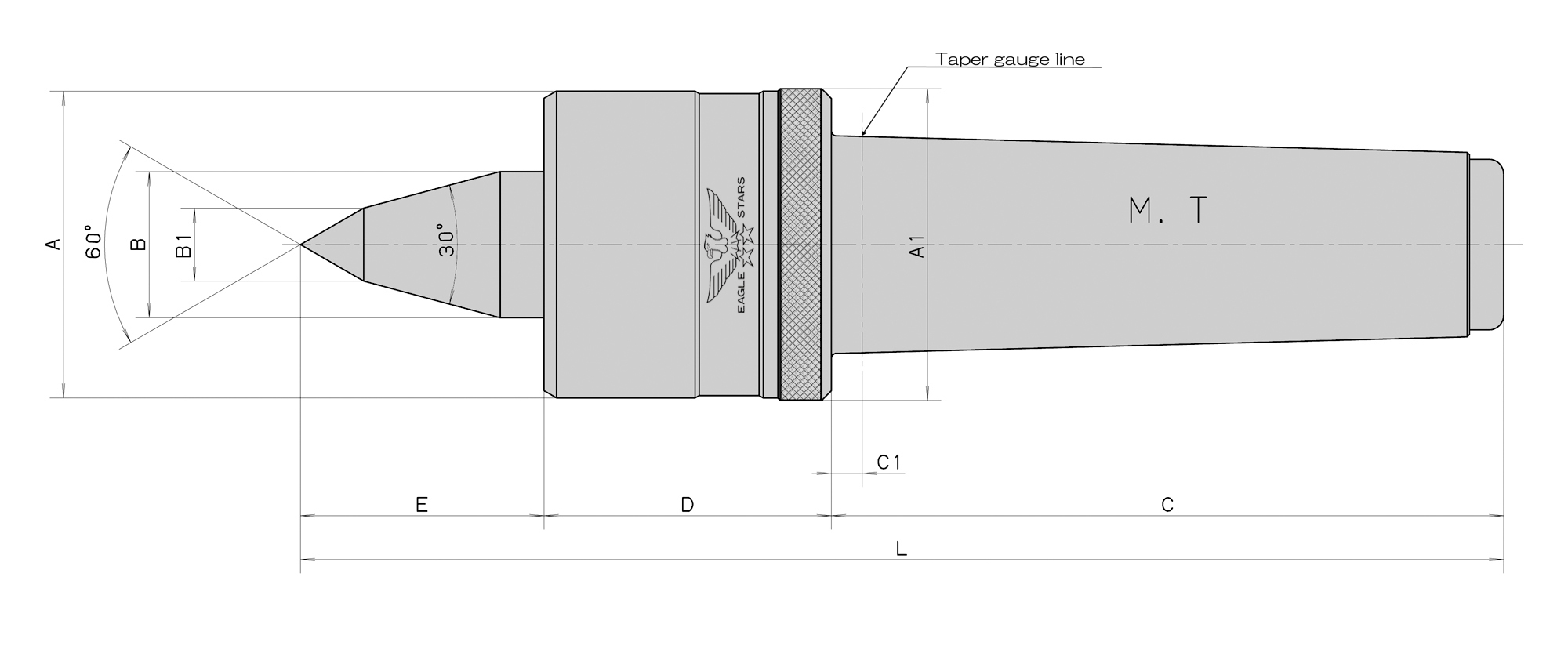
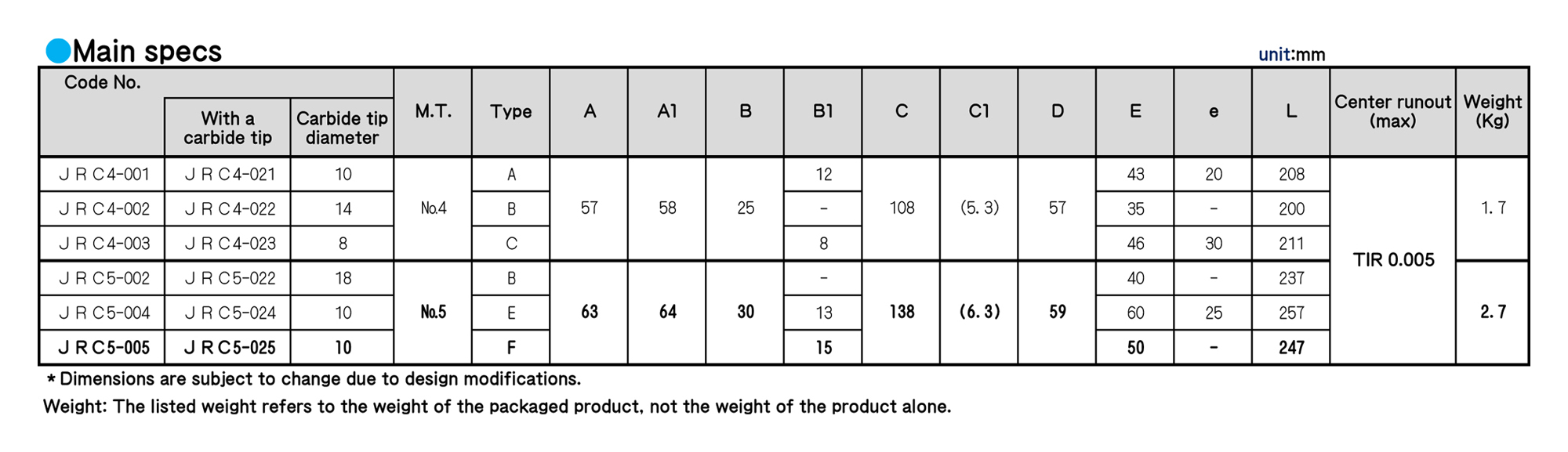
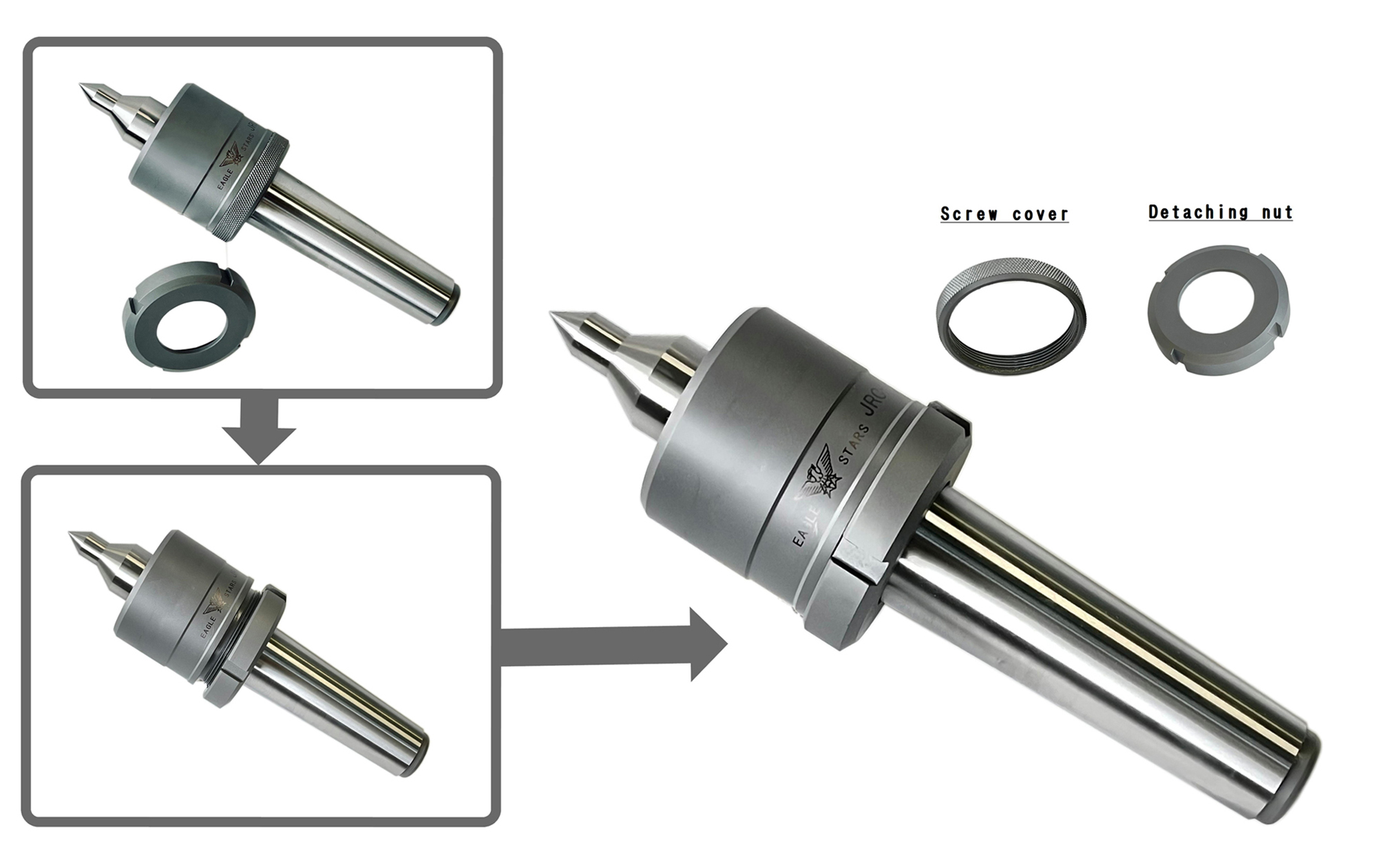
ROLLING CENTERS
ROLLING CENTERS
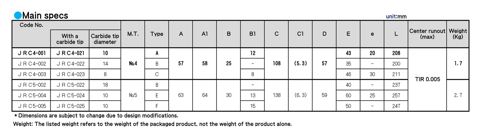
■ Maximum rotation rate: 3,000 revolutions per minute.
■ We incorporate a tapered roller bearing inside JRC for smooth and low torque.
■ Compact body, and easy-to-use rotation range: 500 to 3,000 revolutions per minute
■ A seal is attached as standard.
■ Specs for thin types are available for M. T. No. 4 and M. T. No. 5.
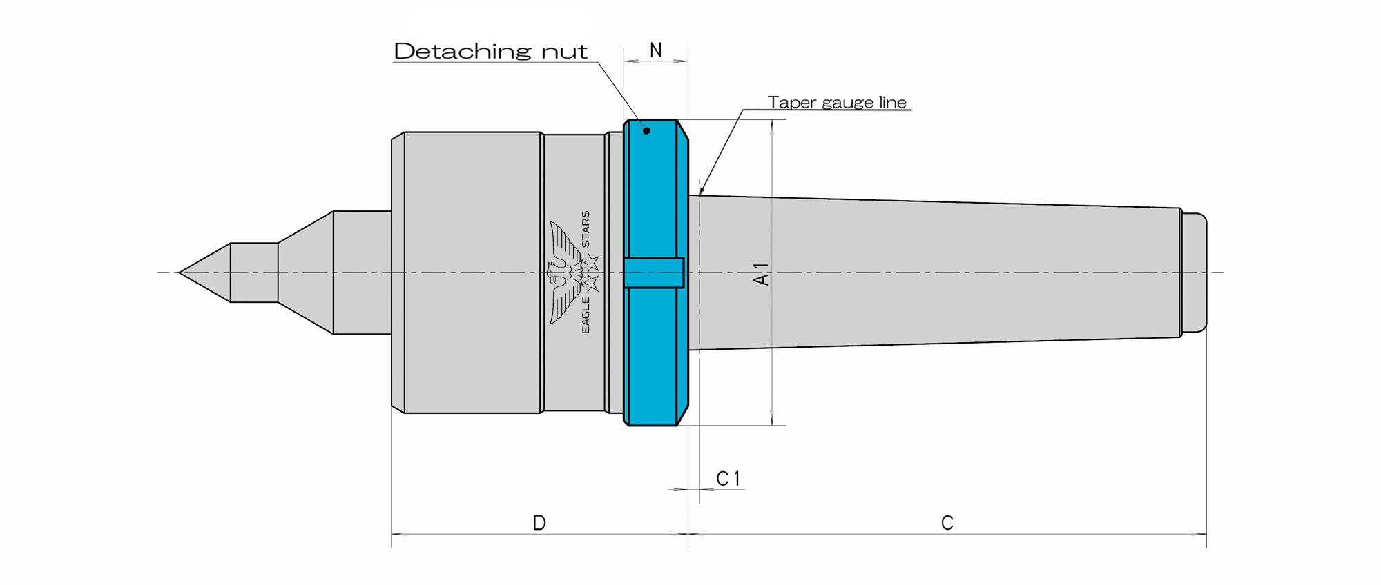
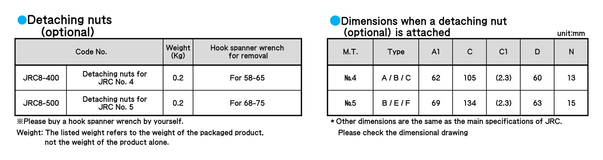
■ Detaching nuts are optional.
ROLLING CENTERS
■ Maximum rotation rate: 3,000 revolutions per minute.
■ We incorporate a tapered roller bearing inside JRC for smooth and low torque.
■ Compact body, and easy-to-use rotation range: 500 to 3,000 revolutions per minute
■ A seal is attached as standard.
■ Specs for thin types are available for M. T. No. 4 and M. T. No. 5.
■ Detaching nuts are optional.
ROLLING CENTERS
ROLLING CENTERS
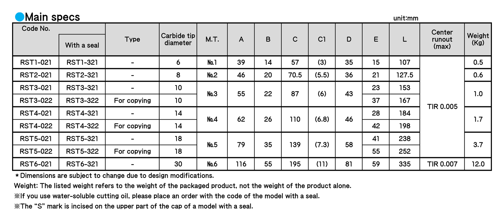
ROLLING CENTERS
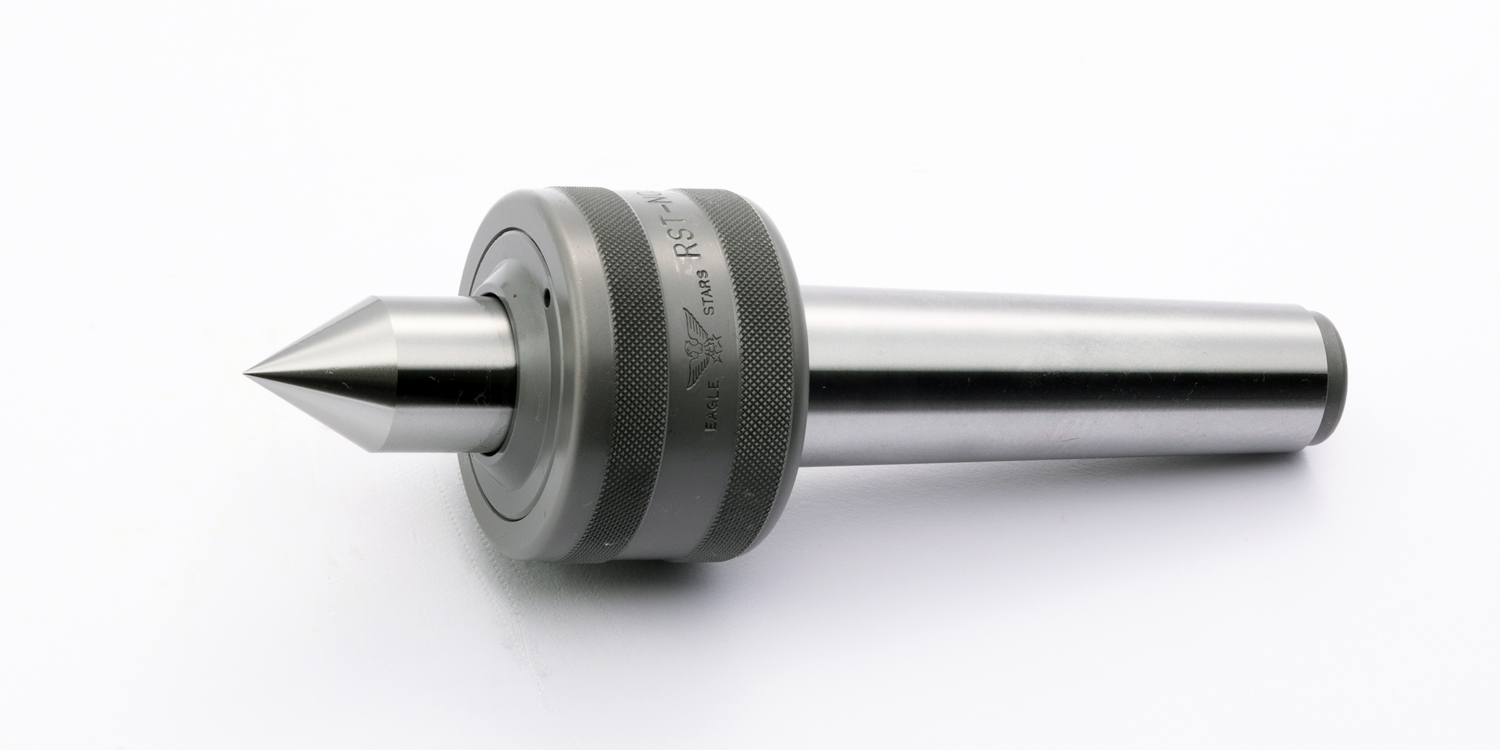
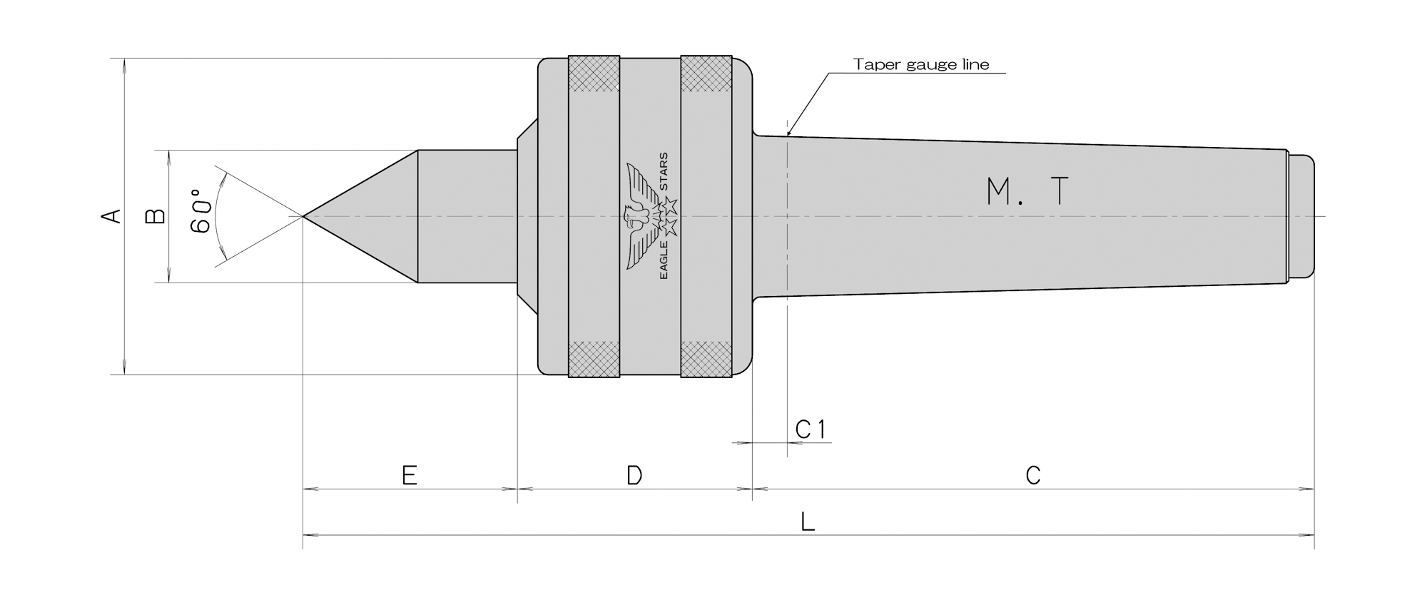
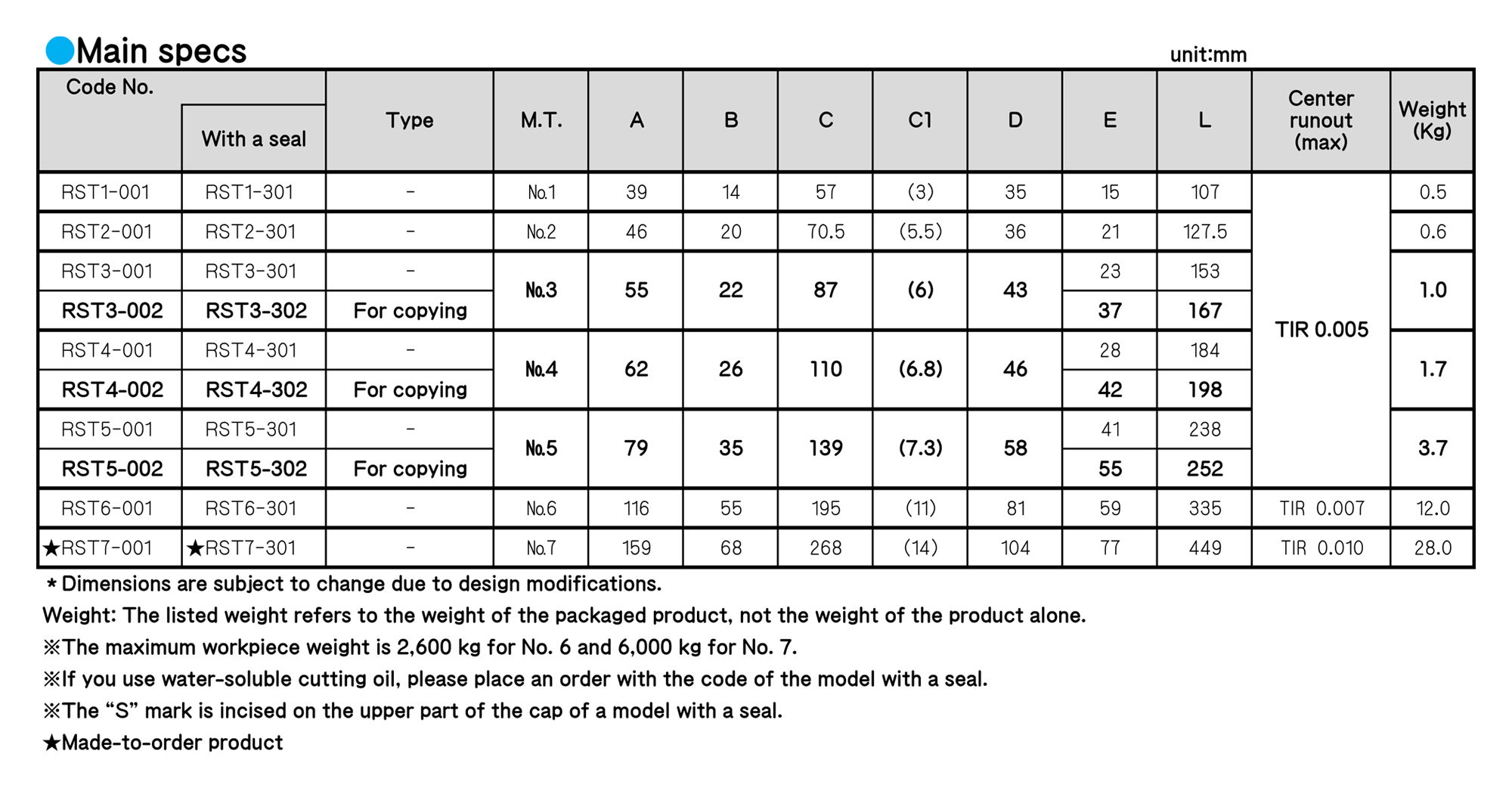
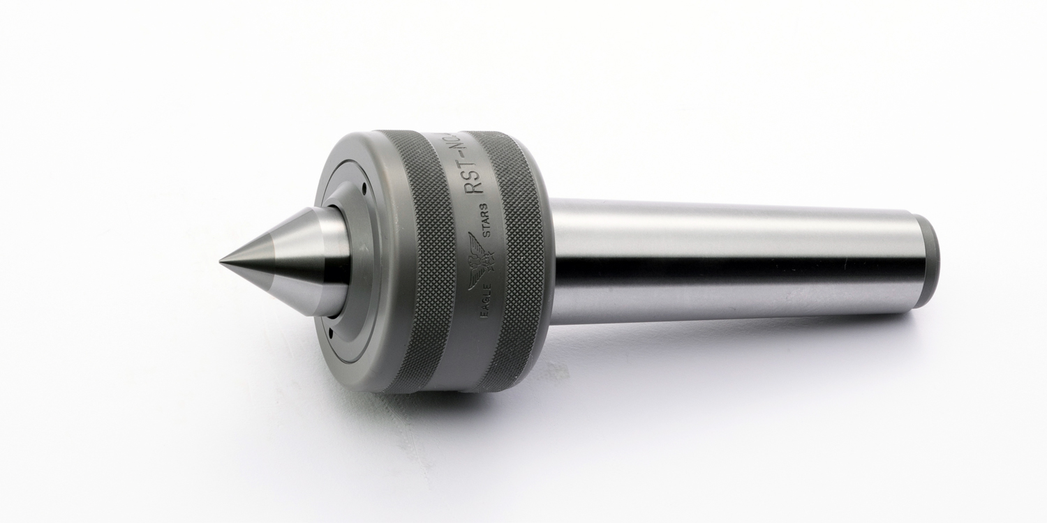
■ RST is suited for the high-stress cutting and the general cutting. The maximum rotation rate is 2,500 revolutions per minute for No. 3 to No. 5.
■ For the inside of RST, two ball bearings and a thrust bearing are used for M. T. No. 1 and No. 2, while a tapered roller bearing, a thrust bearing and a ball bearing are used for M. T. No. 3 to No. 7
ROLLING CENTERS
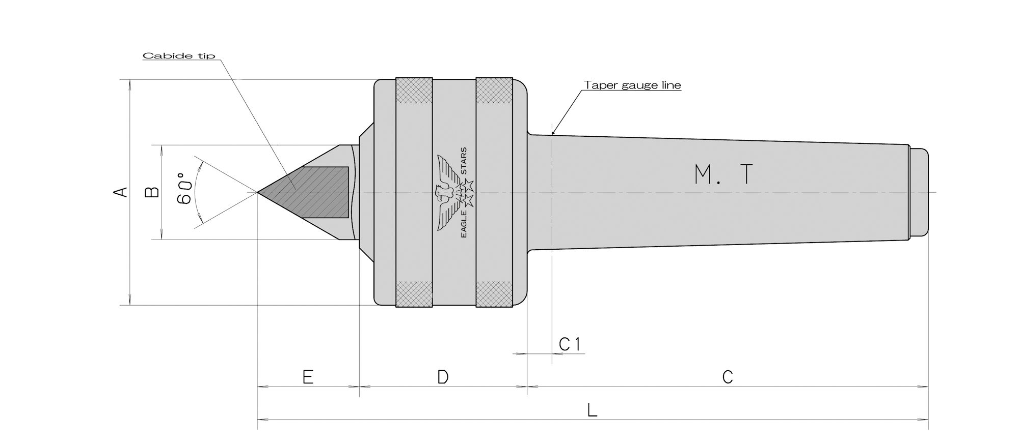
■ The outer appearance, shape and structure are the same as those of the RST type, but a carbide tip is brazed on the tip of the center.
■ Since a carbide tip is brazed on the tip, RST with a carbide tip is excellent in tolerating abrasion and friction.
■ The carbide tip is vulnerable to a shock, Please be careful not to let a workpiece bump against the tip.
ROLLING CENTERS
ROLLING CENTERS
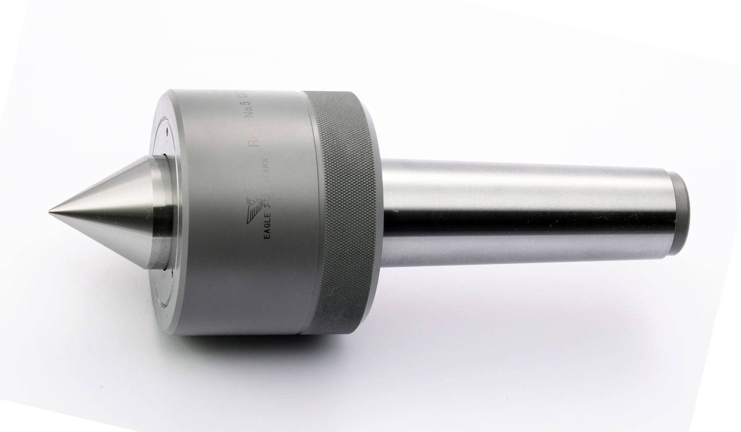
■ To support a heavy workpiece compared with the our other products,a larger bearing is used, and the outer diameter of the body and the diameter of the center shaft are larger.
■ Made-to-order products: φ80-1/10, φ80-1/20 (metric) and φ100-1/20 (metric) can be produced.
ROLLING CENTERS
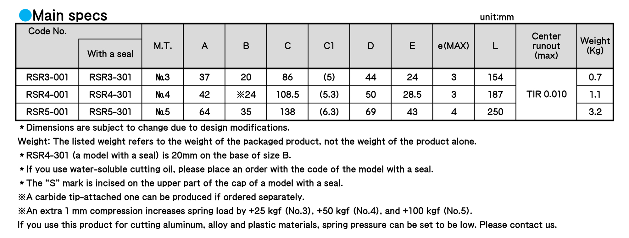
■ Maximum rotation rate is 3,500 revolutions per minute for No. 3, 3,000 revolutions per minute for No. 4 and 2,500 revolutions per minute for No. 5.
■ SR prevents the workpiece from straining and enhances the finishing accuracy because the disc spring inside this product can absorb the elongation of the workpiece generated by processing heat durring cutting.
■ The thrust load generated by the elongation of a workpiece is absorbed by the slide mechanism, so that load will not act on the bearing directly.
Regarding use
■ The initial thrust pressure at the time of setting of max stroke (e dimension: the distance between the cap and the deadline) is set at 50 kgf for No. 3, 100 kgf for No. 4 and 200 kgf for No. 5. When a workpiece is set, push it about 0.5 mm to 1 mm. If you push it for the above e dimension, this model will not show its performance. Please be careful.
※If it is pushed 1 mm compared with the time of initial pressure setting, spring pressure is +25 kgf for No. 3, +50 kgf for No. 4 and +100 kgf for No. 5.
ROLLING CENTERS
ROLLING CENTERS

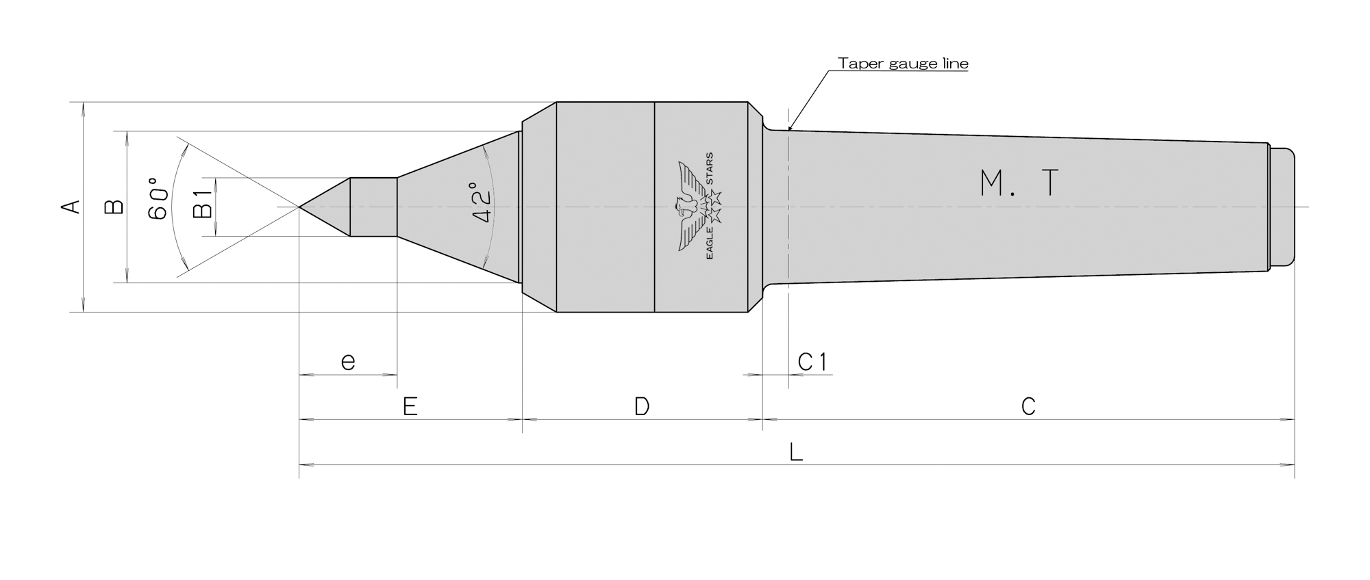
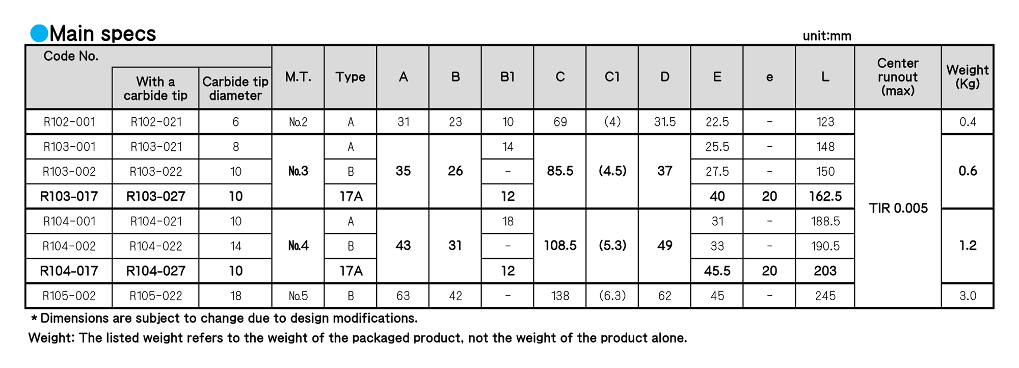
■ 100 with a seal is suited for cutting small workpieces. -17A is suited for thread cutting and end face processing because that tip is thin.
■ We incorporate two needle bearings and a thrust bearing inside 100 with a seal.The body diameter is small.
■ A V seal is adopted. This is optimal when using cutting oil.
Regarding use
■ If there is no load onto the center shaft, the center shaft moves up to 0.5 mm. Please apply thrust at the time of use.
■ Please ensure that the drain hole (water drainage) faces downward at the time of use.
ROLLING CENTERS
ROLLING CENTERS
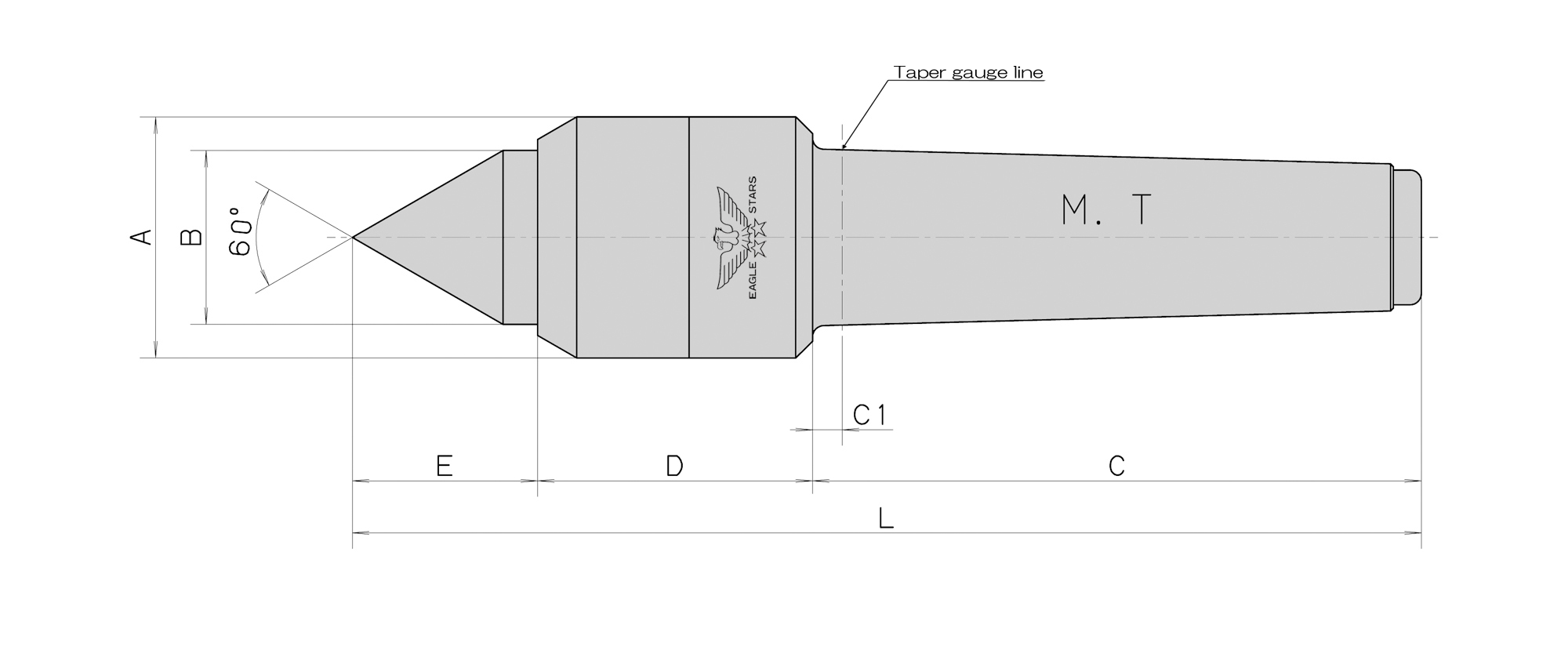
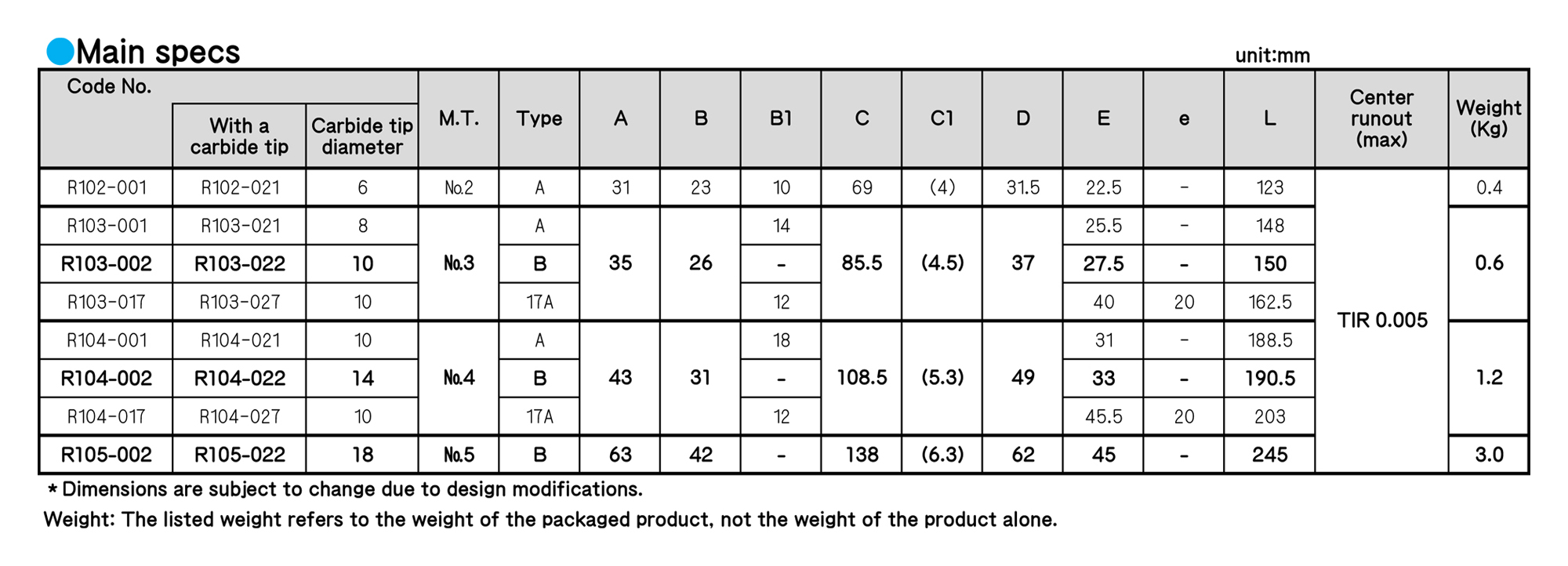
■ Maximum rotation rate is 3,500 revolutions per minute for No.2, 3,000 revolutions per minute for No.3, 3,000 revolutions per minute for No.4 and 2,500 revolutions per minute for No.5.
■ 100 is suited for cutting small workpieces. -17A is suited for thread cutting and end face processing because that tip is thin.
■ We incorporate two needle bearings and a thrust bearing inside 100.The body diameter Is small.
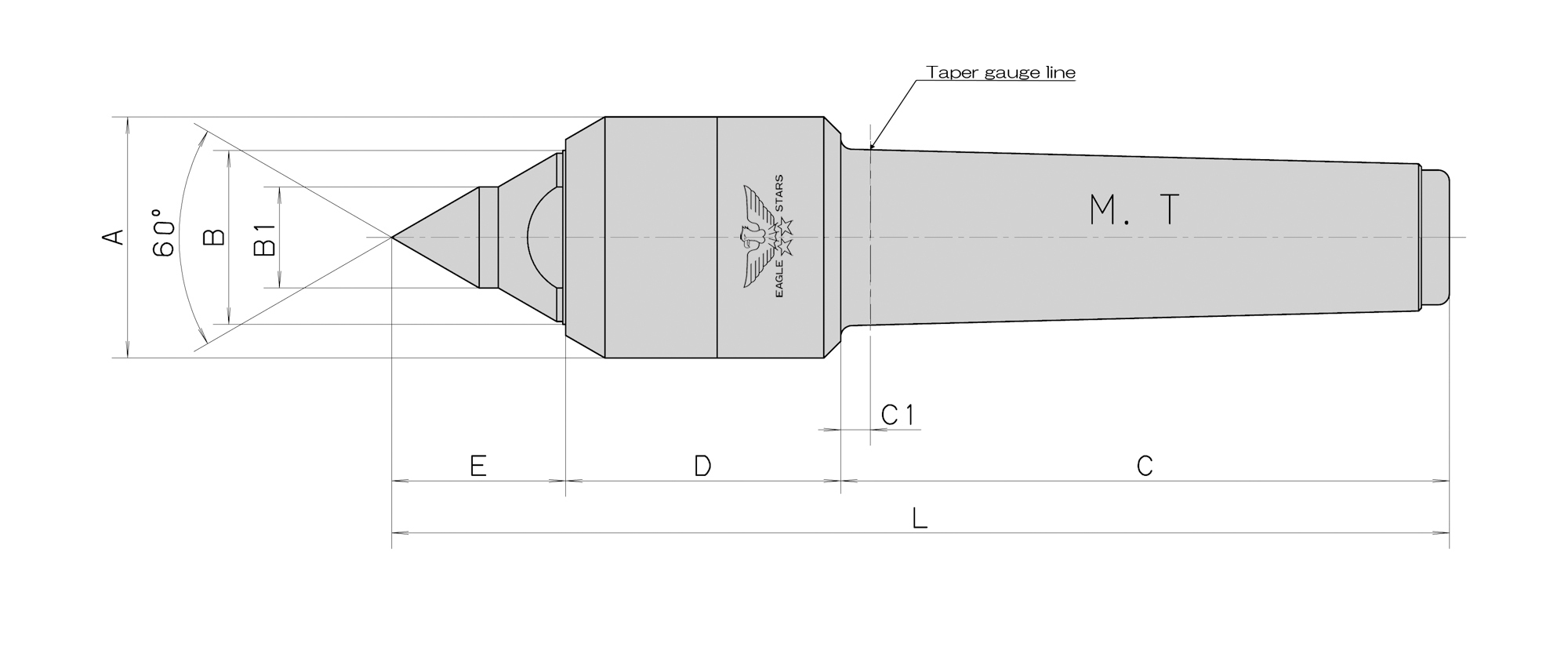
■ We design that the head part of the body is within 60 degrees from the tip of the center not to be affected by a turning tool.
Regarding use
■ If there is no load onto the center shaft, the center shaft moves up to 0.5 mm. Please apply thrust at the time of use.
■ If you use cutting water, etc., choose a model with a seal .
ROLLING CENTERS
■ Maximum rotation rate is 3,500 revolutions per minute for No.2, 3,000 revolutions per minute for No.3, 3,000 revolutions per minute for No.4 and 2,500 revolutions per minute for No.5.
■ 100 is suited for cutting small workpieces. -17A is suited for thread cutting and end face processing because that tip is thin.
■ We incorporate two needle bearings and a thrust bearing inside 100.The body diameter Is small.
■ We design that the head part of the body is within 60 degrees from the tip of the center not to be affected by a turning tool.
Regarding use
■ If there is no load onto the center shaft, the center shaft moves up to 0.5 mm. Please apply thrust at the time of use.
■ If you use cutting water, etc., choose a model with a seal .
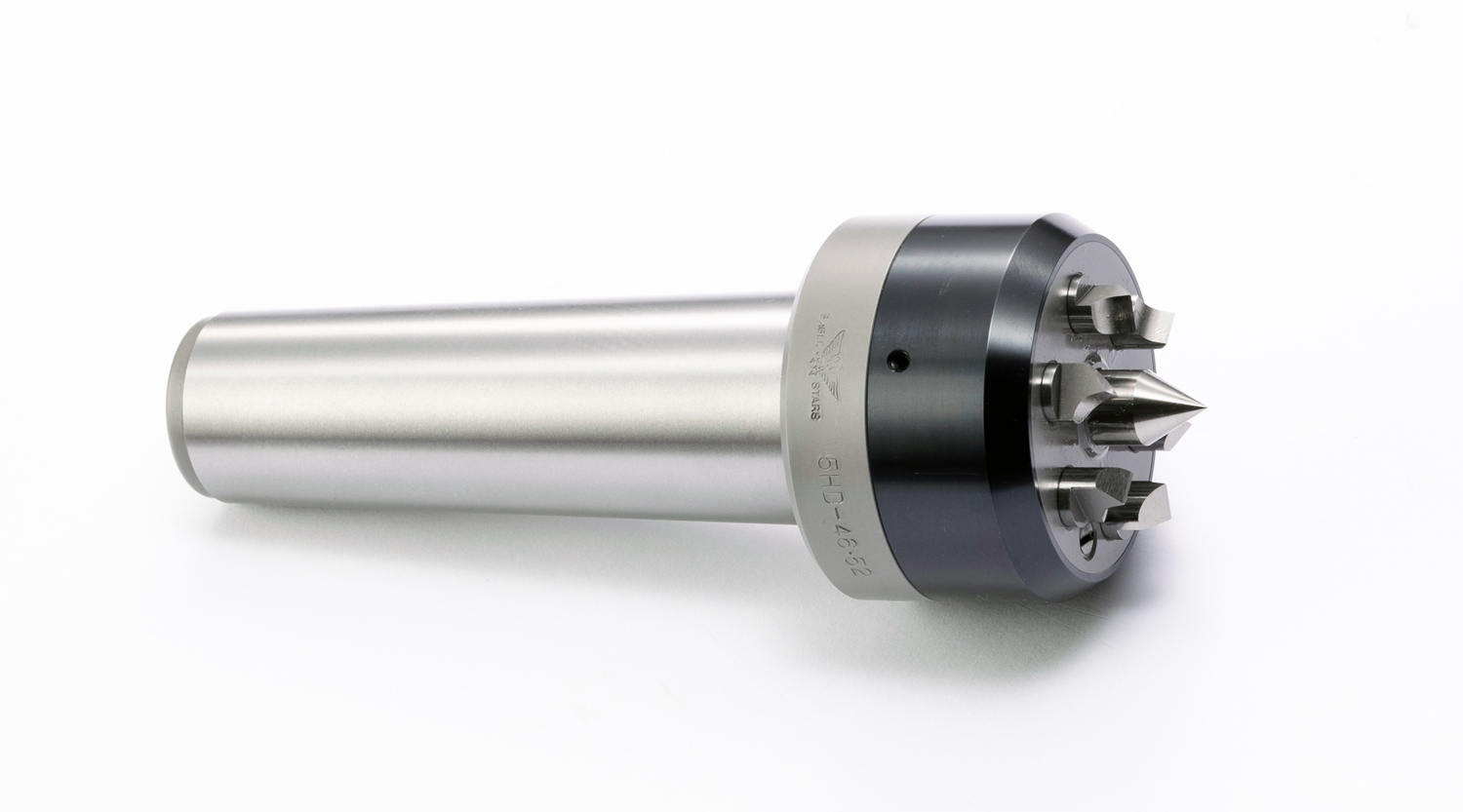
ROLLING CENTERS

Custom-made products〈3-point holding Rolling Centers〉
■ We recommend using it on a grinder / measuring machine.
■ Hollow workpieces and pipe-shaped workpieces tend to have an elliptical shape as shown in Fig. A due to deformation after heat treatment. If you try to hold the center hole with a cone of 60 °, you will hold it at two points.
■ It is possible to hold the center of the work by holding it at 3 points.
◆ The product in the above picture has three carbide tips brazed to the conical tip (60 °).
◆ As shown in Fig. B, we can also manufacture a shape with the tip conical part cut in 3 places.
※We can manufacture it only if the center hole has a small diameter.
ROLLING CENTERS
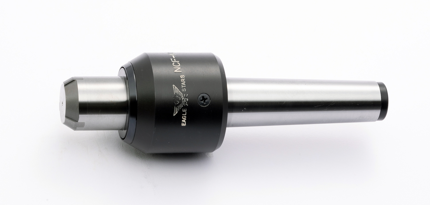
Custom-made products 〈Floating tip〉
■ The flange part in contact with the work floats.
■ There are two floating methods, one using a spherical plain bearing (figure) and the other using a spherical seat type.
■ The tip flange part will be restored by O-ring rubber.
■ The flange part in contact with the work can be replaced depending on the dimensions.
◆ When you process the outer diameter part of flange-shaped workpieces (pressed products, gears, etc.), an arbor collet grasps the inner diameter part.
◆ It can be used when you want to hold it under surface pressure, such as a workpiece without a center hole.
ROLLING CENTERS
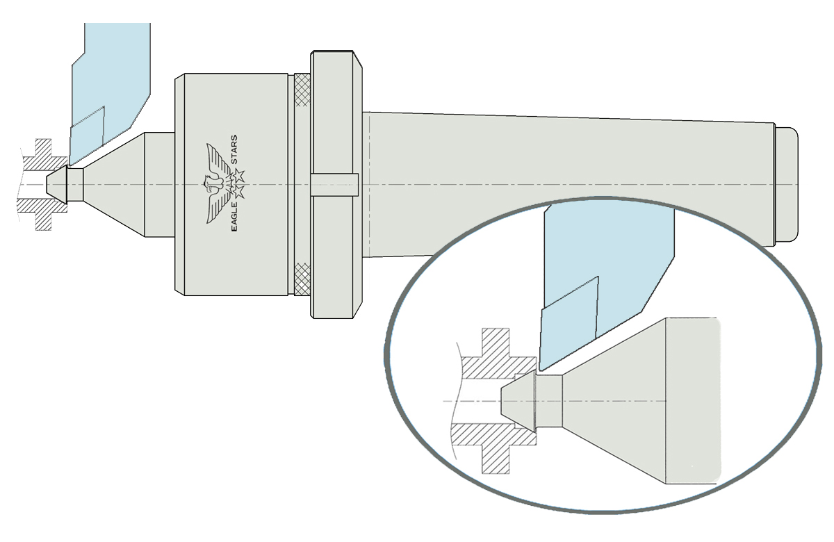
Custom-made products 〈For end face processing〉
■ It is possible to process from the end face of the work piece by making the tip into an arrowhead shape.
ROLLING CENTERS
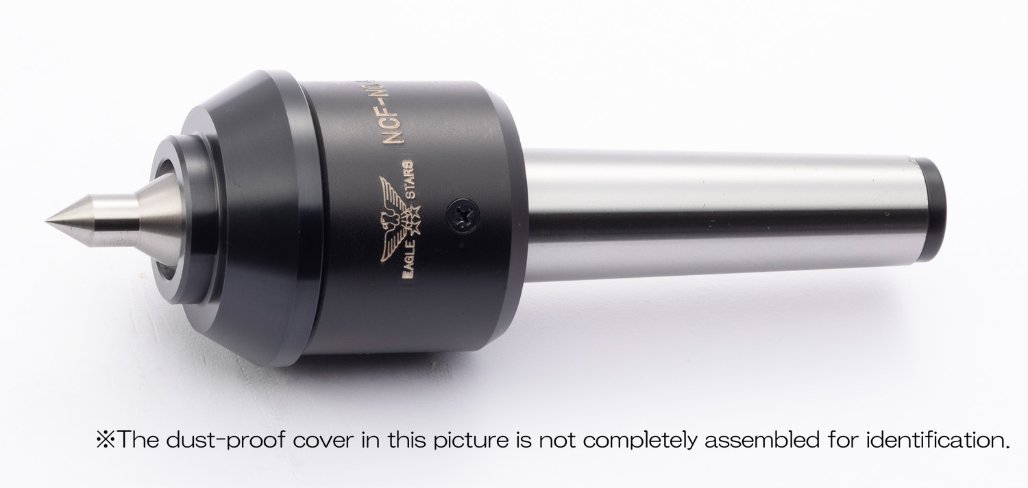
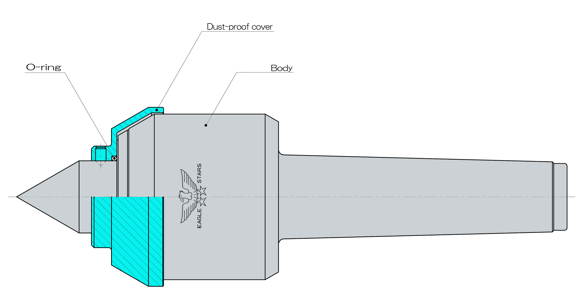
Custom-made products 〈Dust-proof cover〉
■ We recommend a rolling center with a dust-proof cover as follows:
The coolant is applied directly to the seal part.
Abrasive powder and coolant sludge have invaded and are in trouble.
The labyrinth seal and V seal cannot prevent the intrusion of coolant.
You want to install it on the underside of a vertical lathe.
◆ Please order the dustproof cover as a set with the body.
ROLLING CENTERS
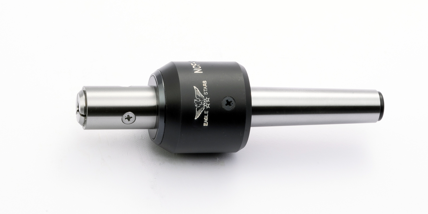
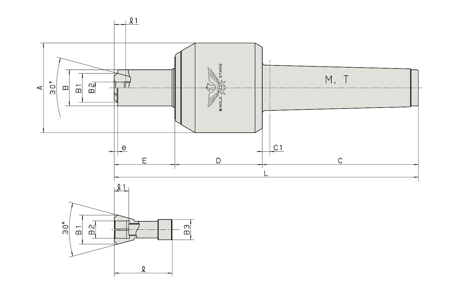
Custom-made products〈With a collet chuck 〉
■ The center shaft has a built-in collet chuck. When you press a workpiece, a (thrust) collet chuck enches and grips a workpiece.
■ The collet chuck center is suited for cutting and grinding outer diameter-based workpieces, such as the shafts of motors, copies, printers and fax machines,rubber rolls.
■ The collet chuck center can process workpiece withont center holes.
■ We can produce a stationary collet chuck center.
※When placing an order, please notify us of the collet dimension you want (B2 = gripping diameter, ℓ1 = depth). We will estimate the turnaround time and price for the product.
ROLLING CENTERS
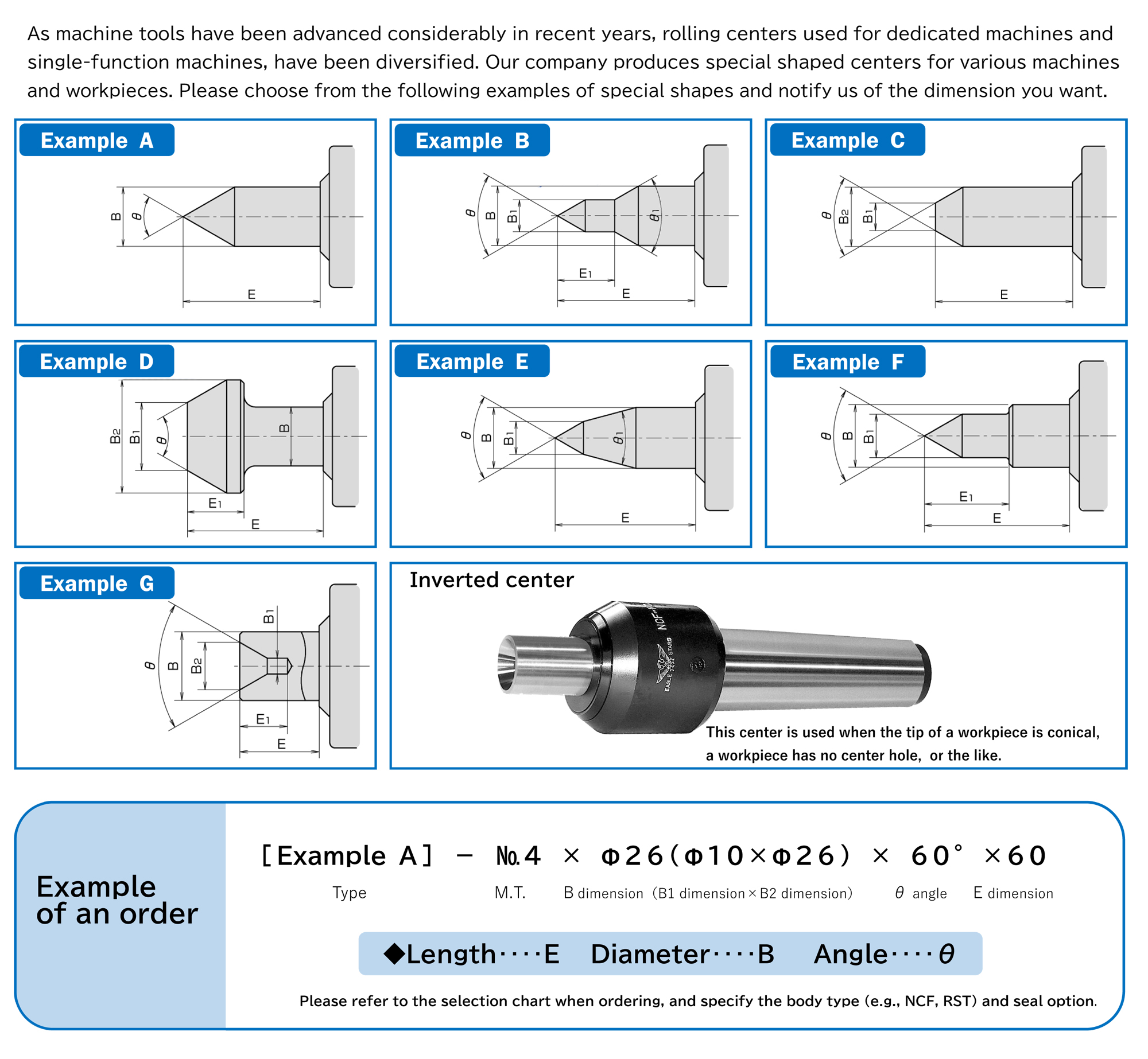
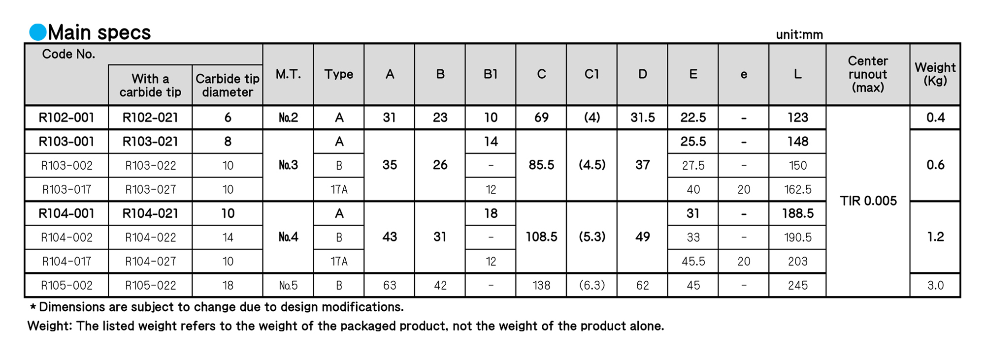
■Note: Dimension B (center shaft diameter) is related to the bearing body. Please select from standard rolling centers whenever possible.
■*We will estimate the turnaround time and price for the product.
■As machine tools have been advanced considerably in recent years, rolling centers used for dedicated machines and single-function machines, have been diversified. Our company produce spccial shaped centers for various machines and workpieces.
Please choose from the examples of special shapes and notify us the dimension you want.
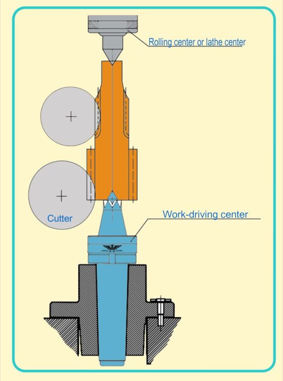
WORK-DRIVING CENTERS
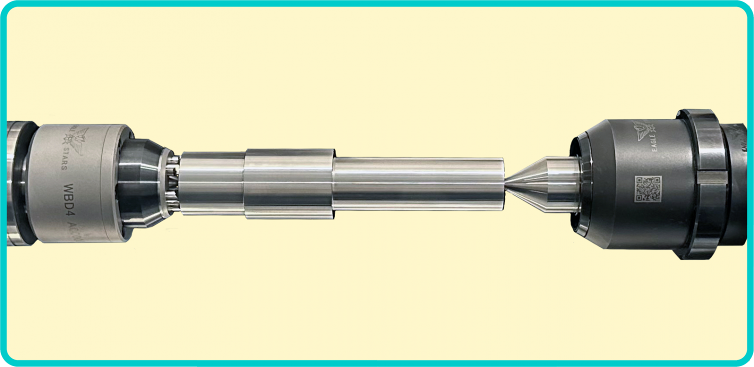
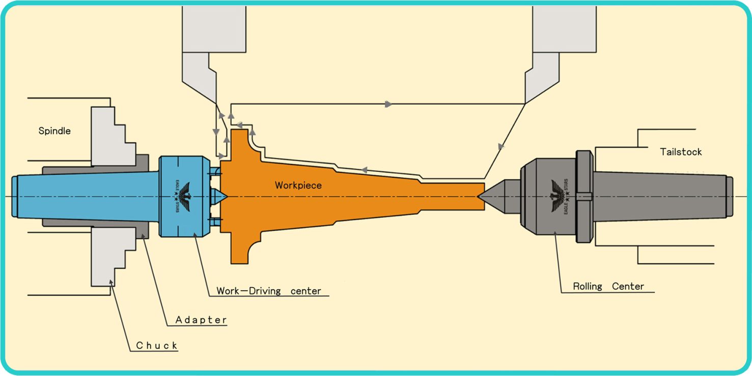
■ The work-driving center has jaws, which grasp the inclined edge face evenly.
■ This product does not need the gripping margin of the chuck for holding the end face of a workpicce and enables a curting process without inverting the workpiece. Therefore,this causes a reduction of materials and time and uniformarizing precision.saves materials and time and equalizes precision.
■ When the work-driving center processes with both center holes,it does not need a lathe dog and it can improve the process the process efficency.
■ After this product is mounted on a machine, you do not need to handle this product.
■ Using the adapter for the work-driving center allows users to attach the work-driving center to the chuk easily.
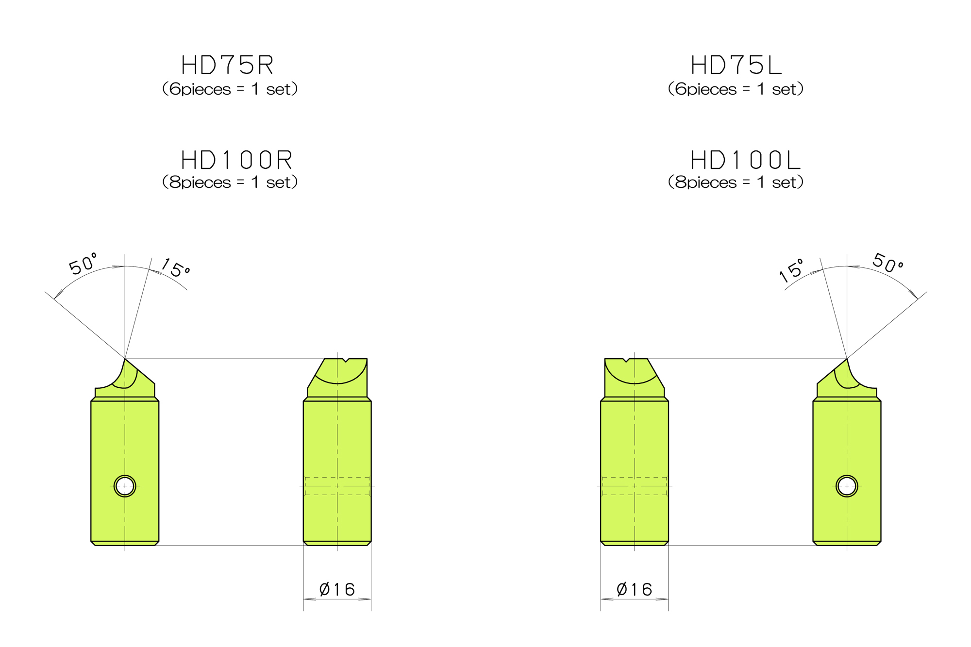
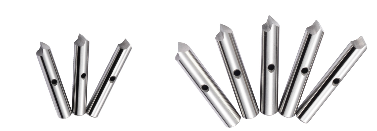
■ If the jaws wear off or are damaged, we can supply spare jaws.
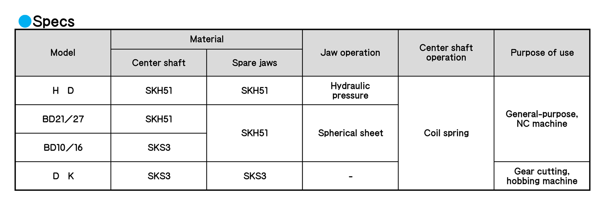
WORK-DRIVING CENTERS
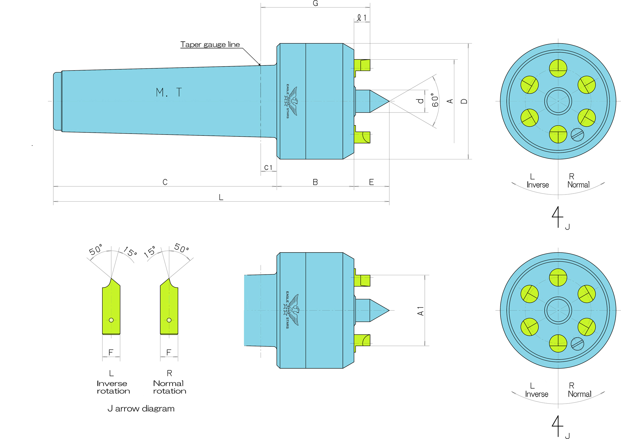
■ The jaw operation adopts a hydraulic mechanism. This mechanism enables jaws to operate independently and to grab the end faces evenly.
■The jaws and the center shaft, which are made from high-speed steel, achieves high durability.
Regarding use
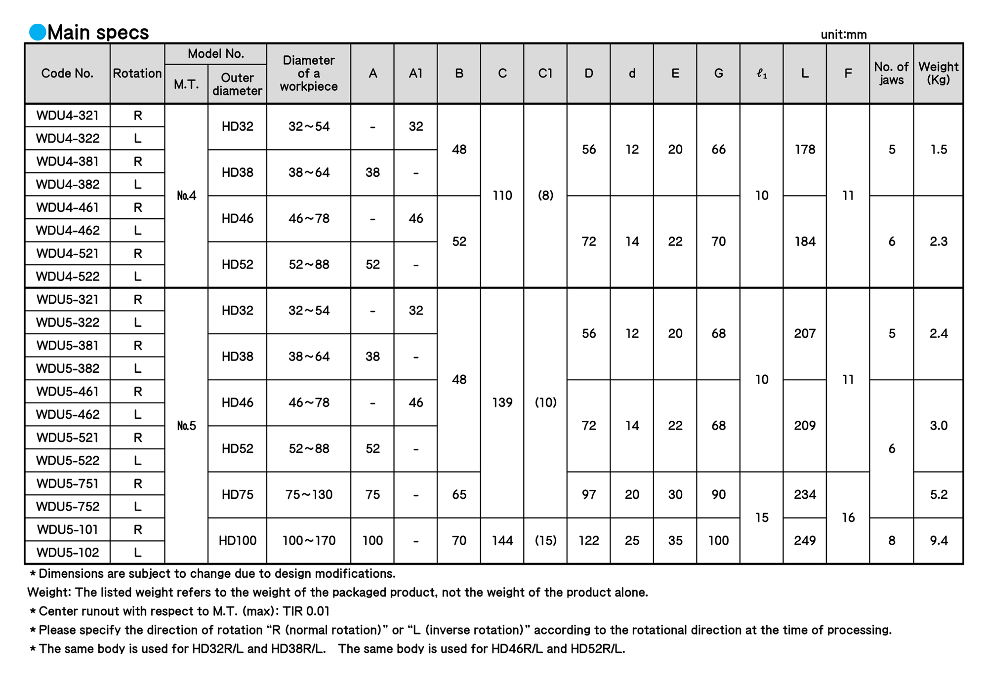
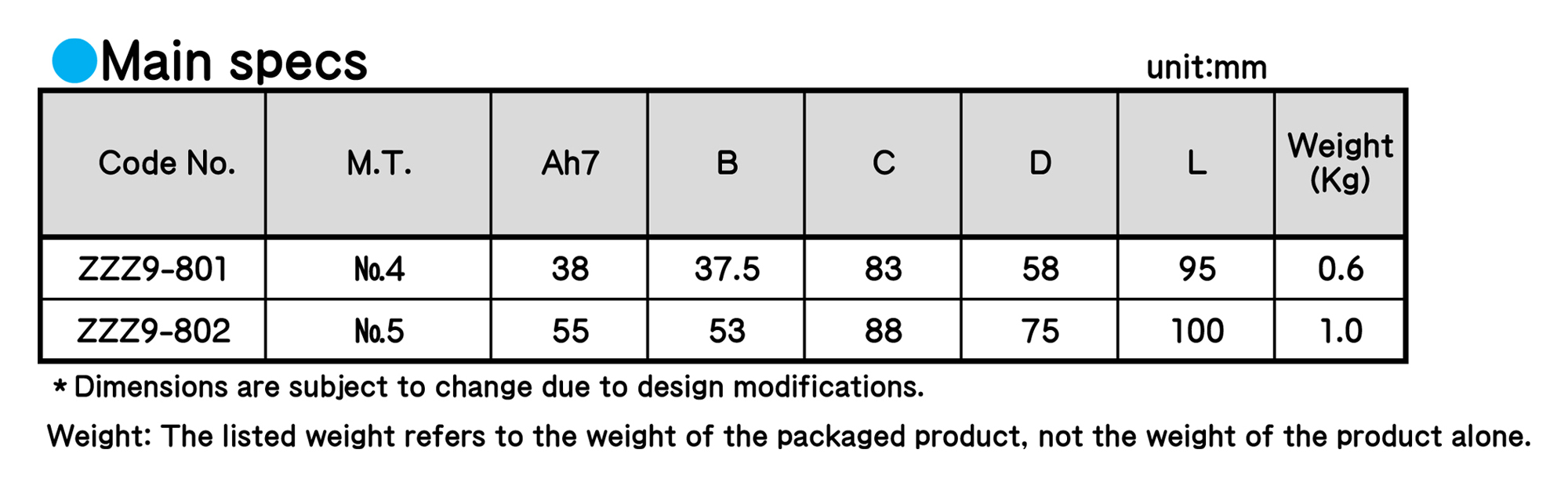
■ It is unnecessary to replenish oil for the hydraulic pressuremechanism, but if the height of every jaw (ℓ1 in the specs table (P.25)) is as follows, please replenish working oil.
HD32/38, HD46/52 ⇒ 7.5 mm HD75, HD100 ⇒ 12.5 mm
■ The center hole (mouth diameter) of each workpiece shall be within the following range.
HD32/38 = 8 mm or less HD46/52 = 10 mm or less HD75 = 14 mm or less HD100 = 10 mm to 20 mm
■ Allowable thrust
HD32/38 = 1,000 kgf HD46/52 = 1,200 kgf HD75 = 2,400 kgf HD100 = 3,200 kgf
■ Please check the rotational direction at the time of processing, and specify R (normal rotation) or L (inverse rotation).
■ Please contact us about hard materials such as thermal refined steel.
WORK-DRIVING CENTERS
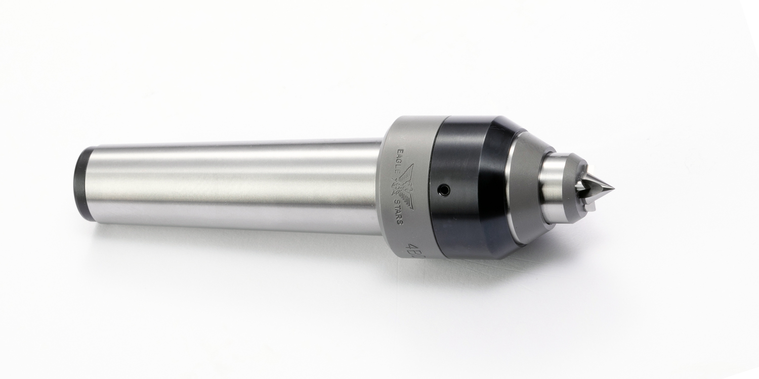
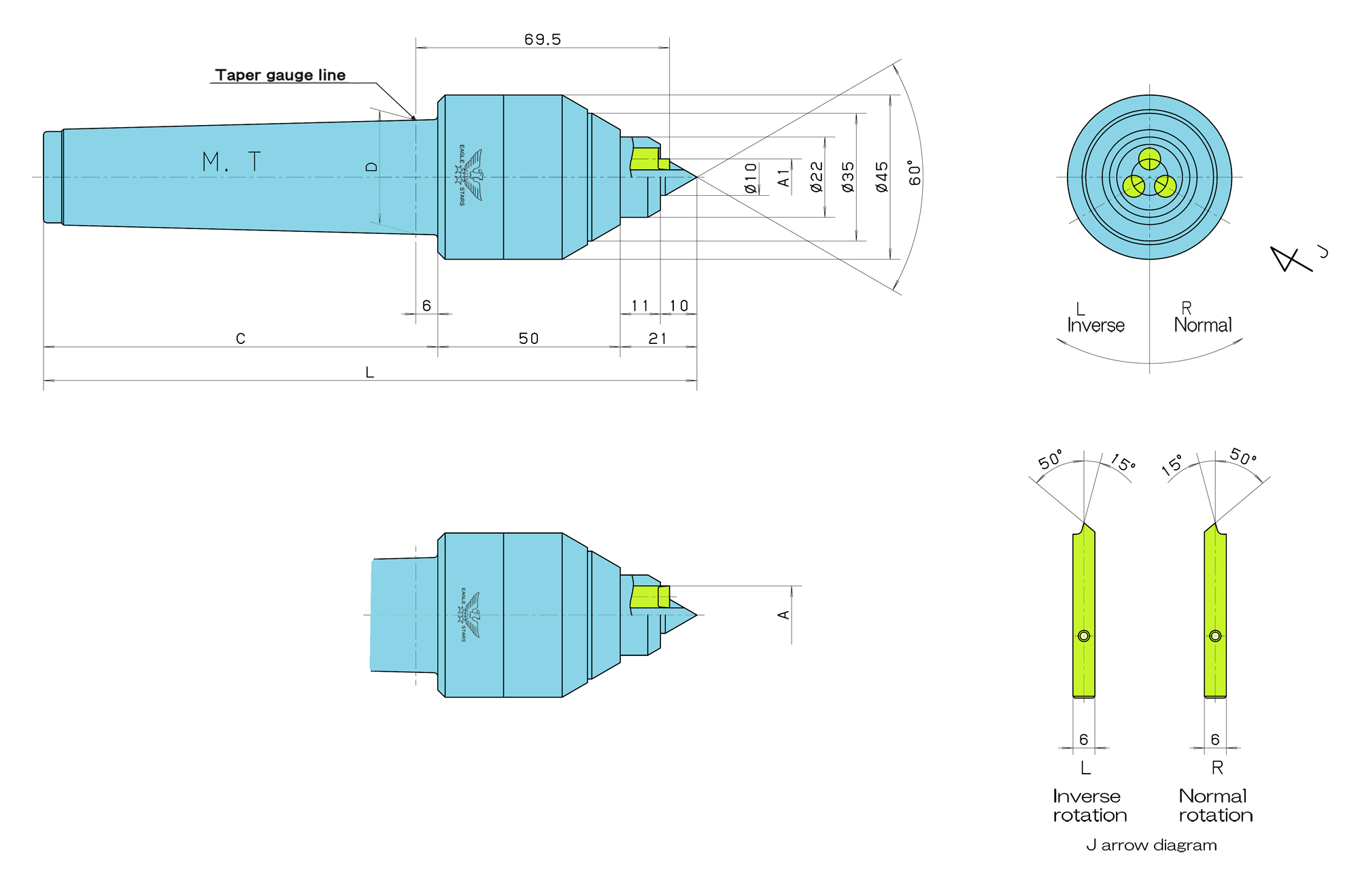
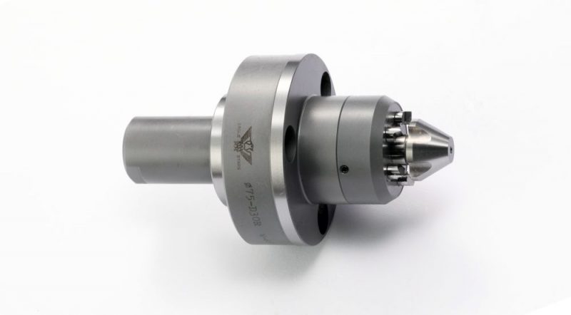
This model is suited for turning a small-diameter workpiece.
■ This model secures a longitudinal dimension because the spherical sheet receives the thrust acting on the jaws.
■ The flat support improves the abrasion resistance and driving force of the jaw operation part.
■ The improvement of the center shaft achieves the long-term stability of precision.
■ Maintenance property is improved.
Regarding use
■ The center hole (mouth diameter) of each workpiece shall be within the range of 2 to 6 mm.
■ If the jaws wear off or are damaged, we can supply spare jaws
■ Please specify “R (normal rotation)” or “L (inverse rotation)” according to the rotational direction at the time of processing. Choose the counterclockwise direction “R (normal rotation)” or the clockwise direction “L (inverse rotation),” seeing the spindle.
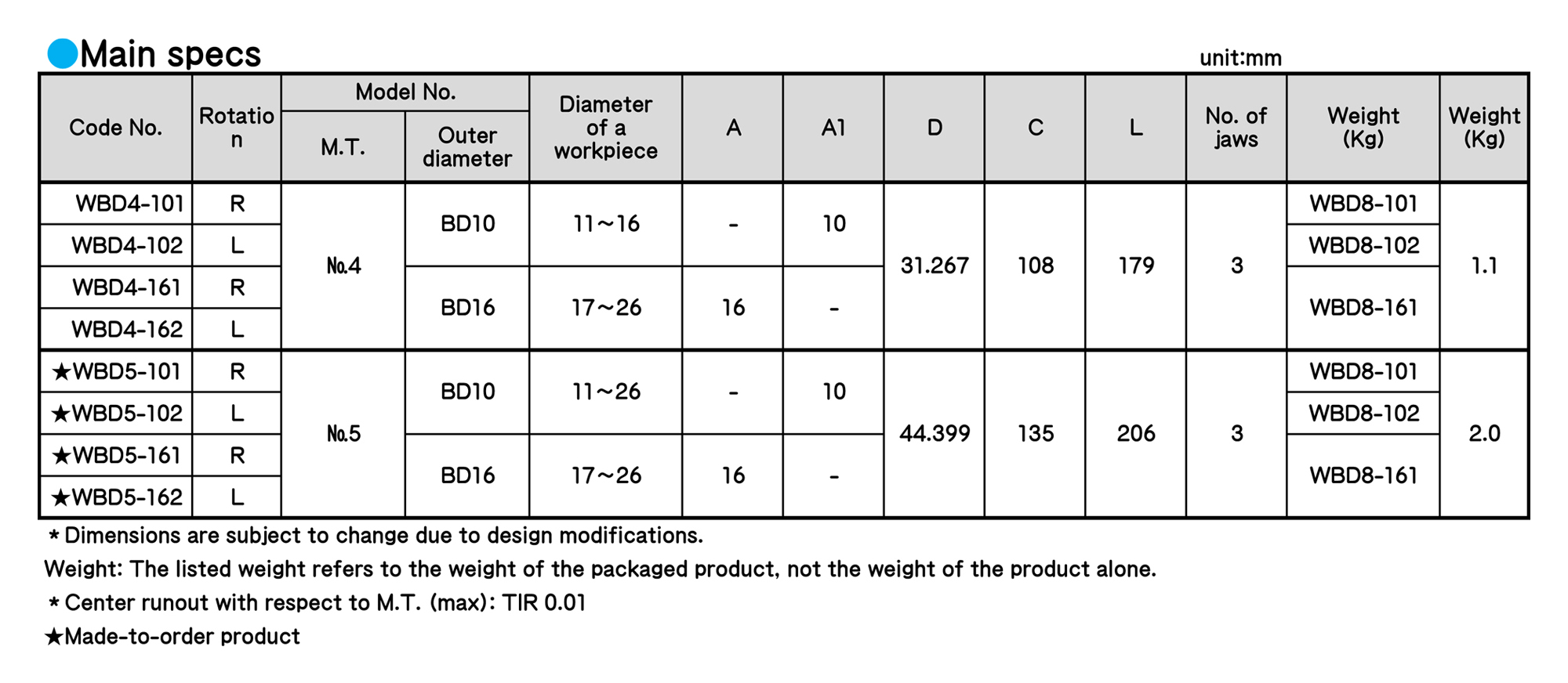
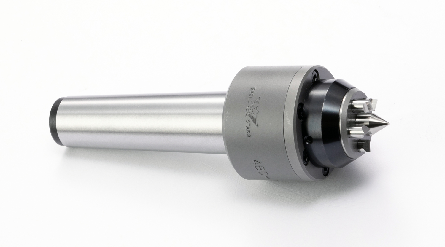
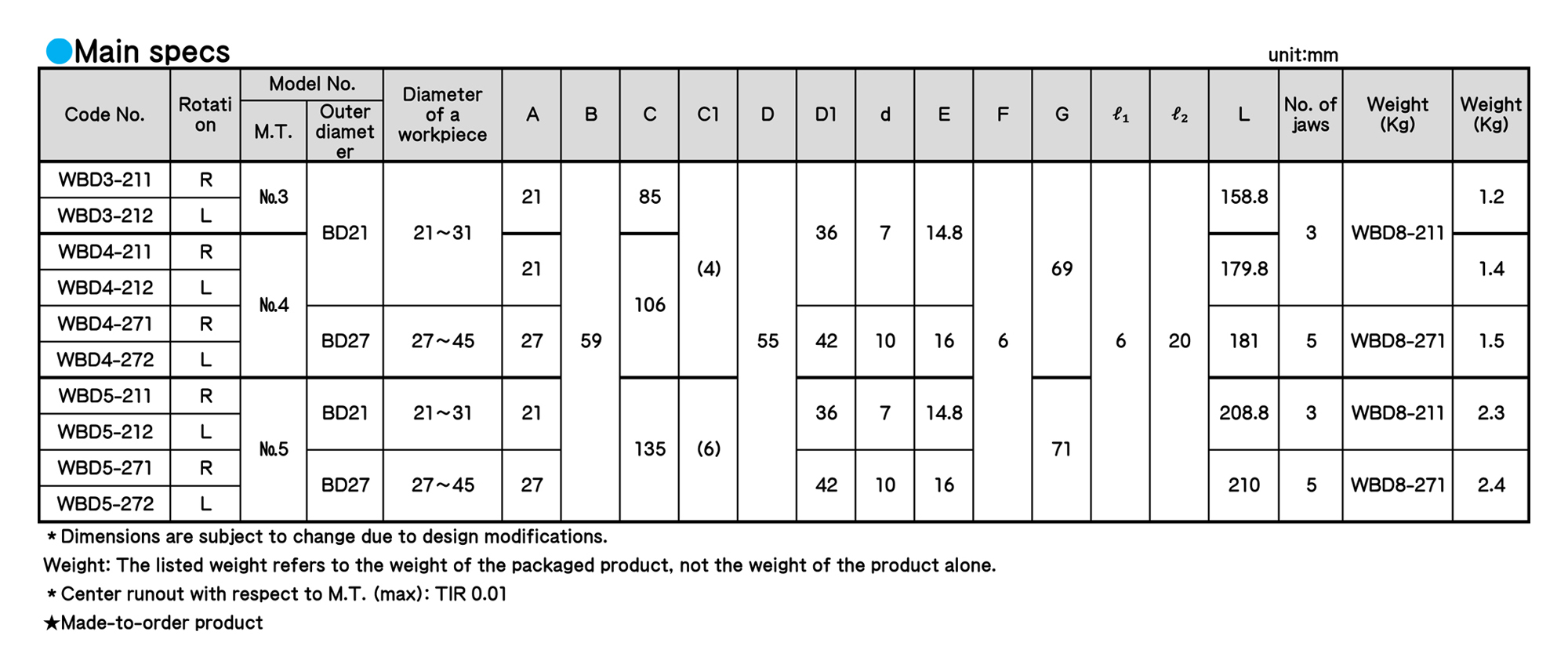
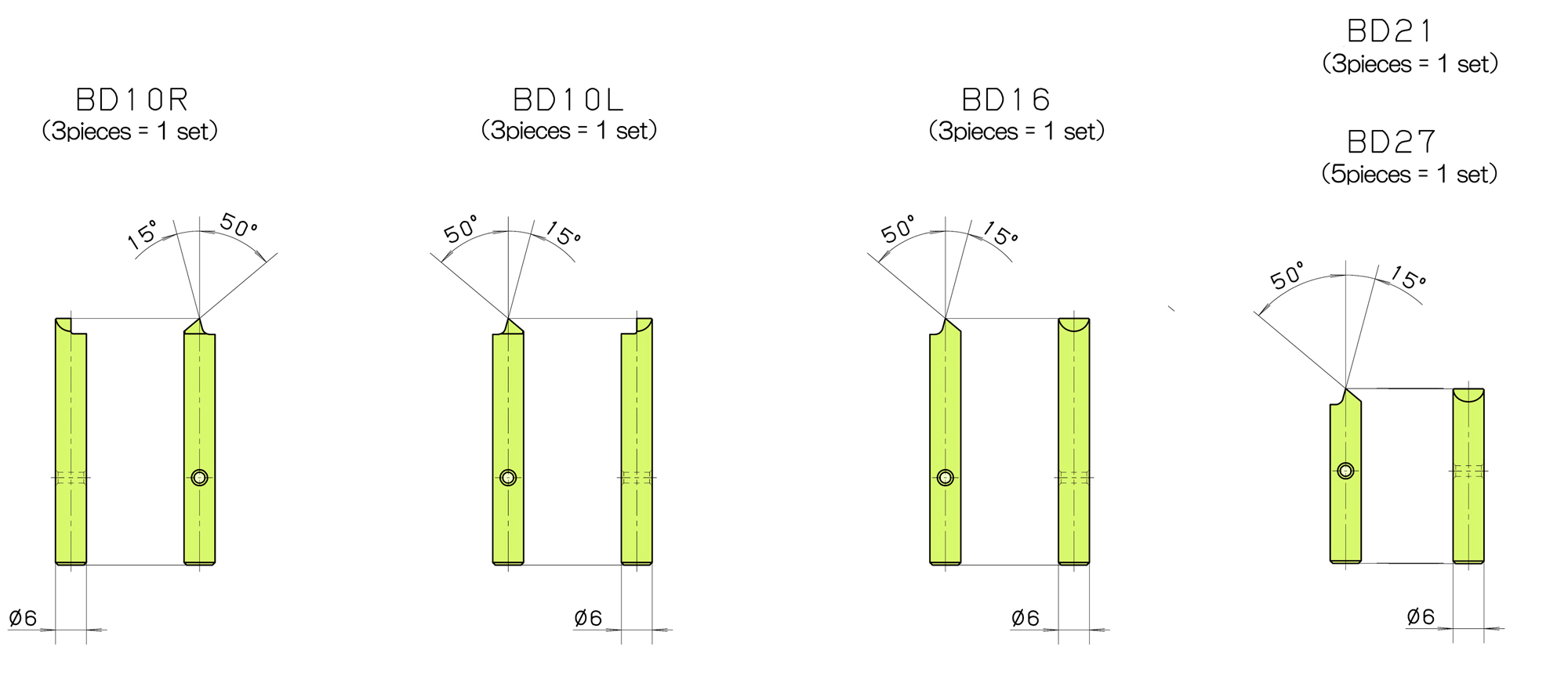
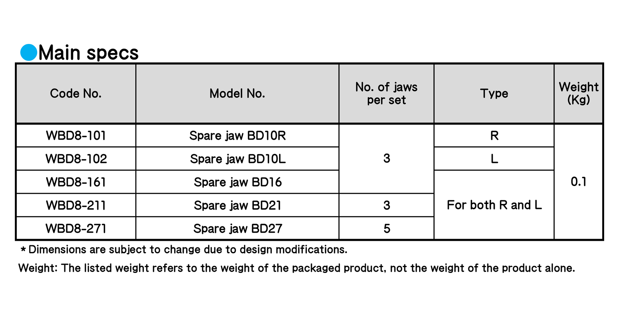
WORK-DRIVING CENTERS
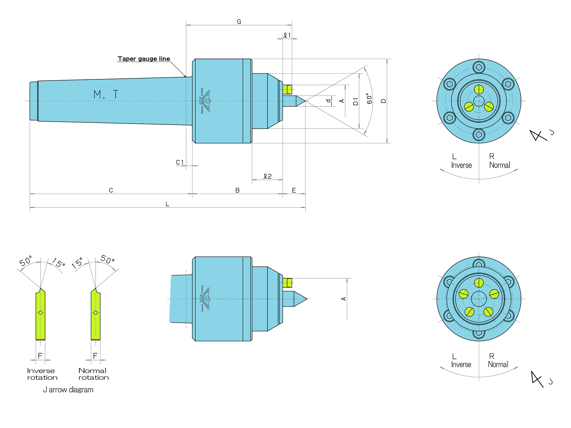
■ This model secures a longitudinal dimension because the spherical sheet receives the thrust acting on the jaws.
■ The flat support improves the abrasion resistance and driving force of the jaw operation part.
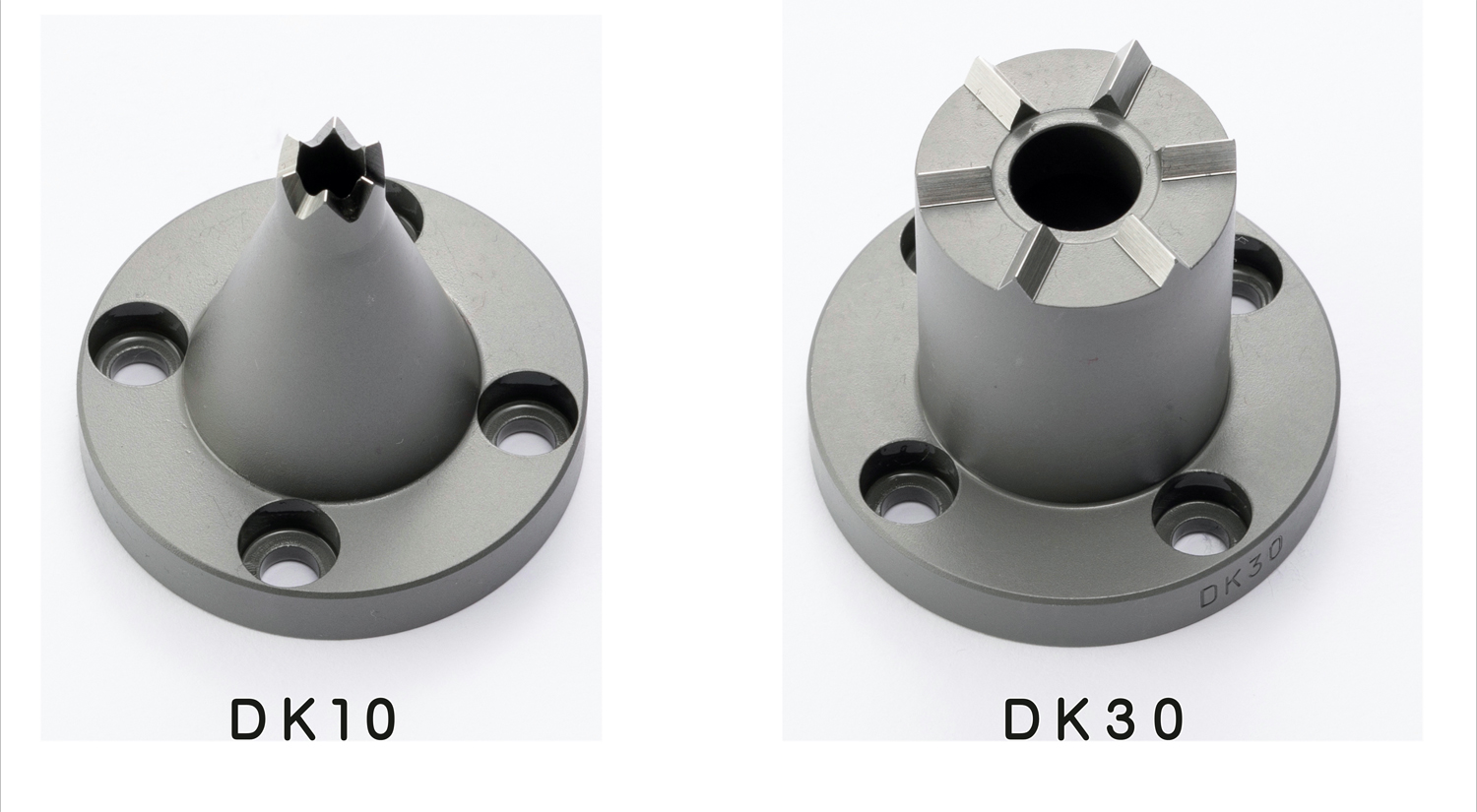
■ BD21 has three jaws, while BD27 has five jaws.
■ Maintenance property is improved.
Regarding use
■ The center hole (mouth diameter) of each workpiece shall be within 2-6 mm for BD21 and 2-8 mm for BD27.
■ If the jaws wear off or are damaged, we can supply spare jaws
■ Please specify “R (normal rotation)” or “L (inverse rotation)” according to the rotational direction at the time of processing. Choose the counterclockwise direction “R(normal rotation)” or the clockwise direction “L (inverse rotation),” seeing the spindle.
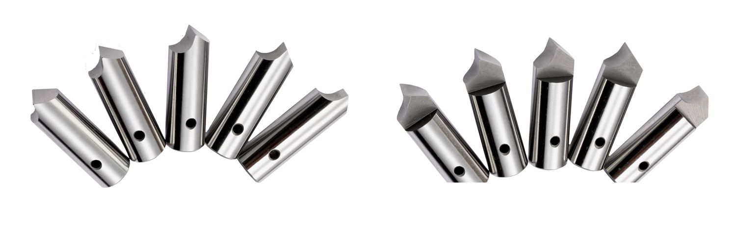
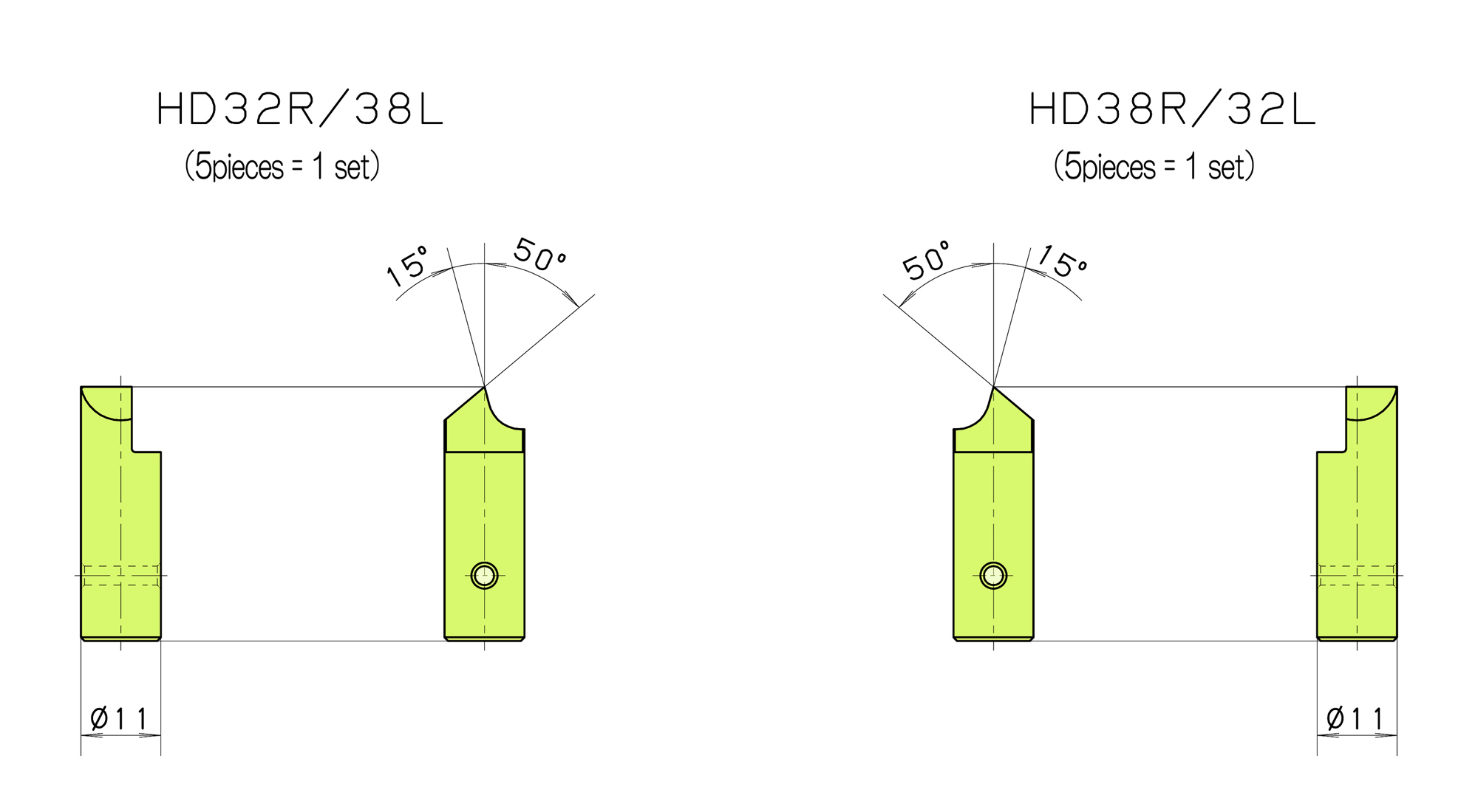
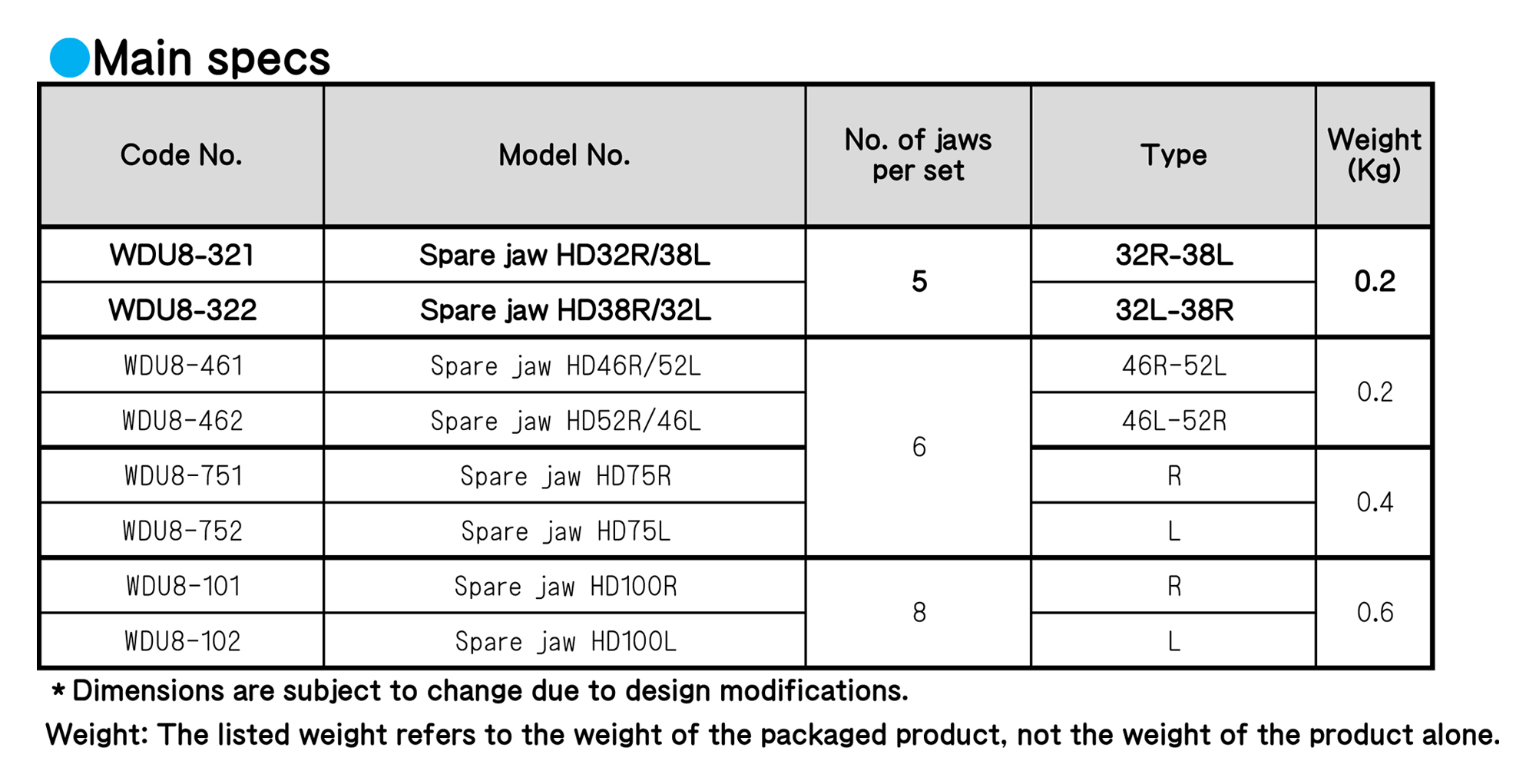
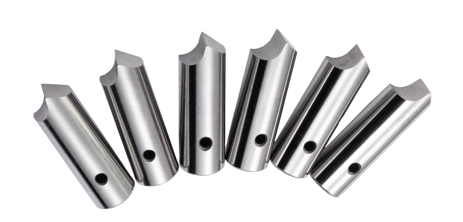
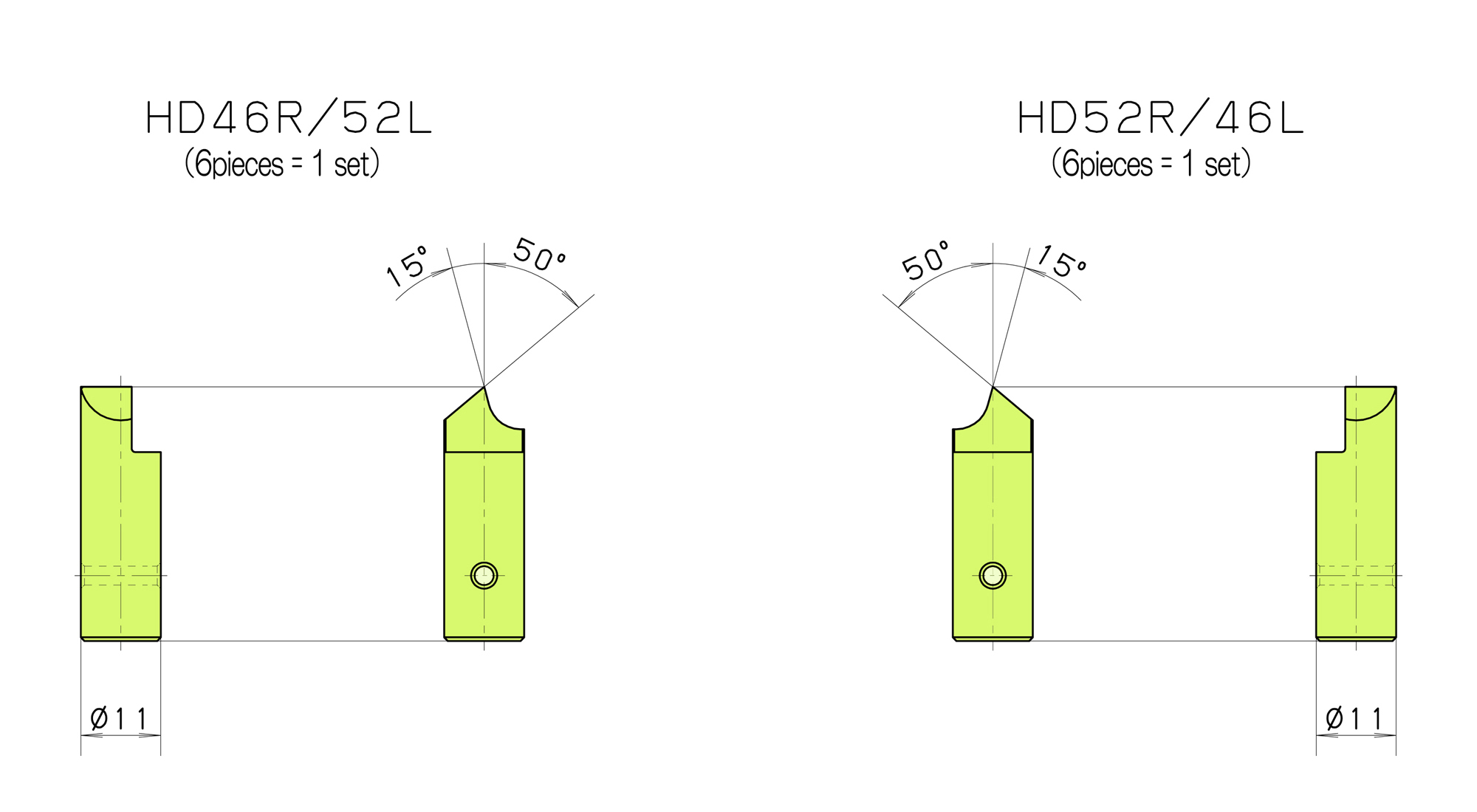
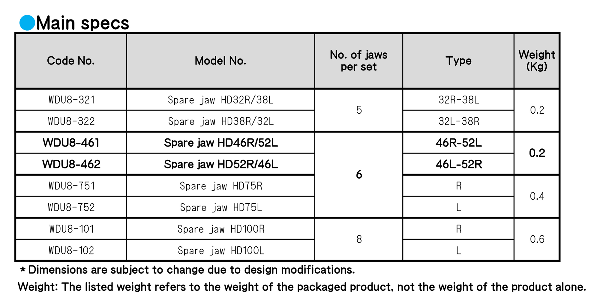
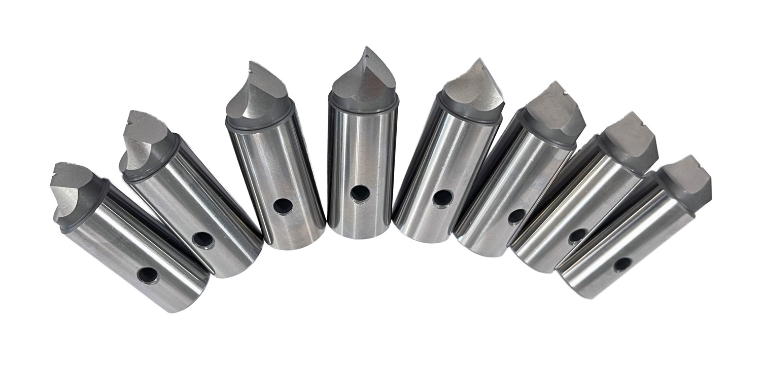
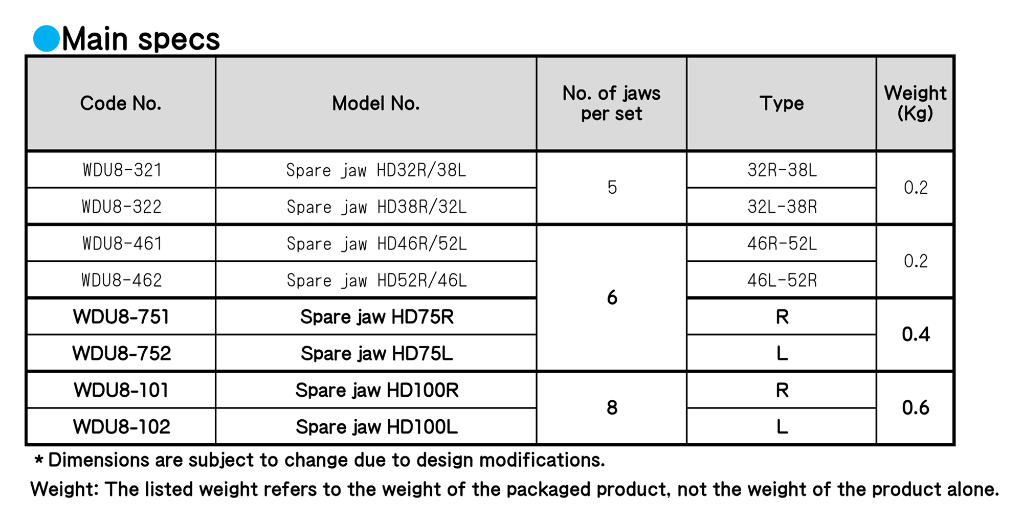
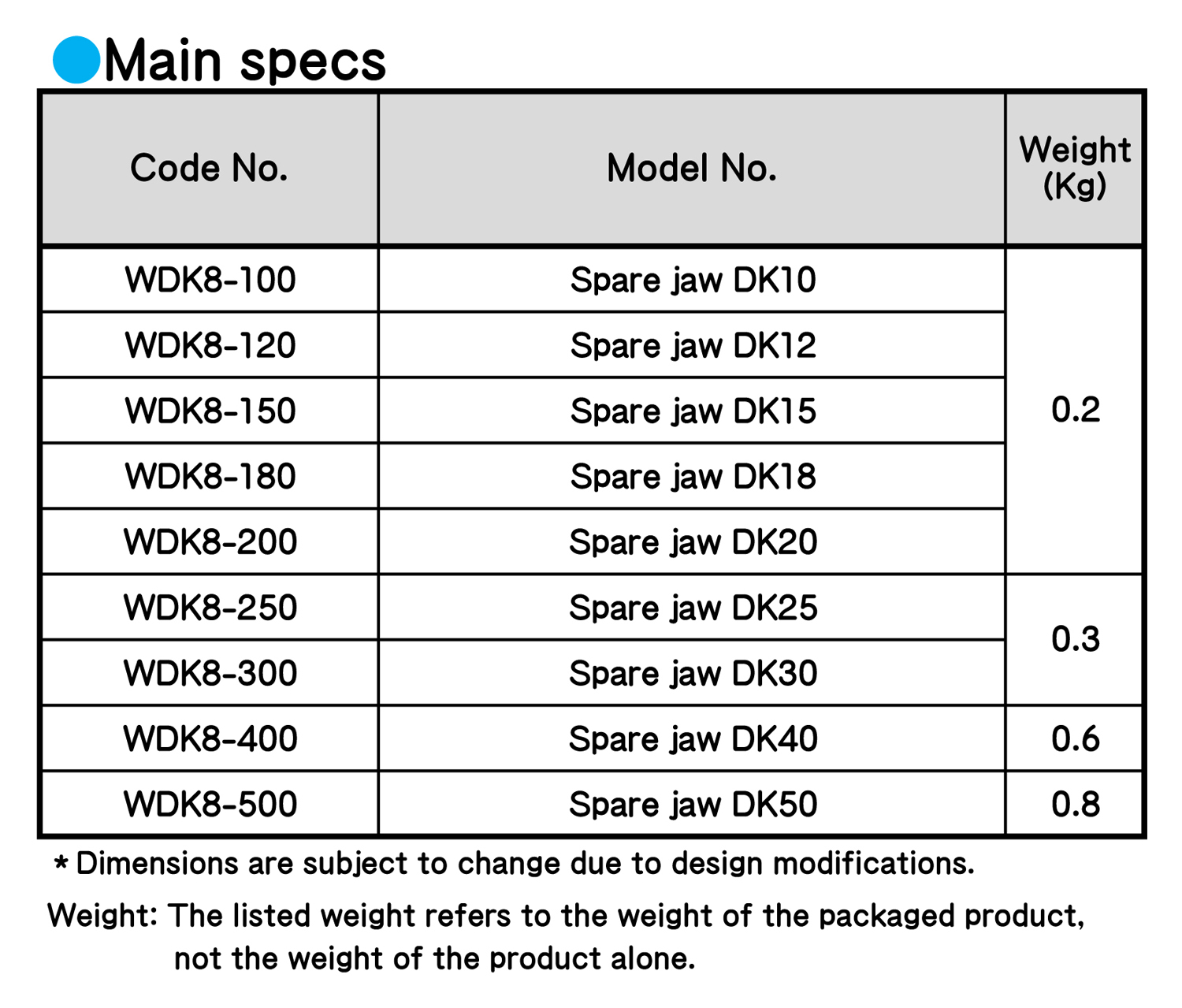
WORK-DRIVING CENTERS
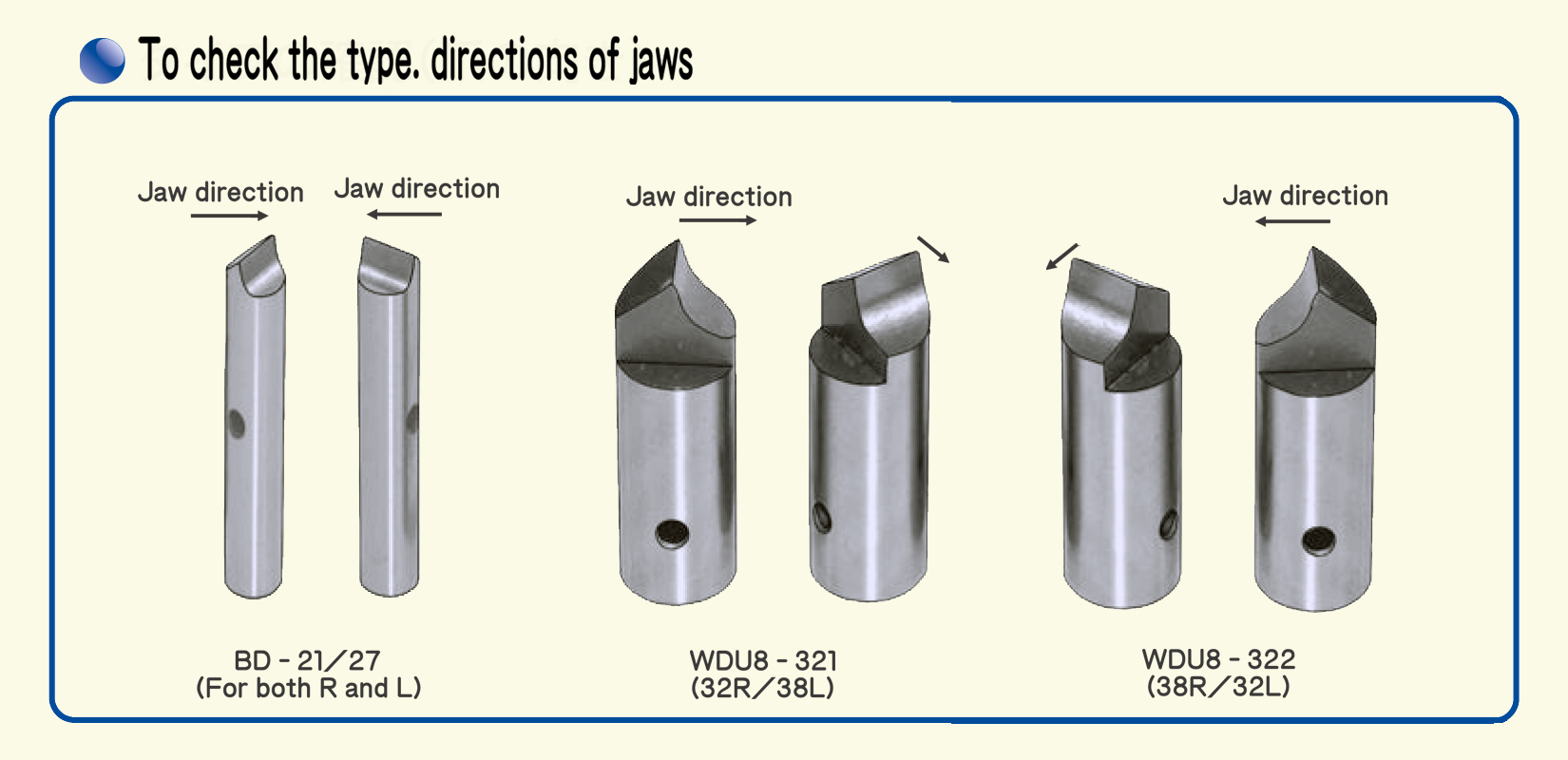
■ If a jaws of work-driving center wears off or is damaged, please replace it with a spare jaws immediately.
■ When ordering a spare jaws, please check the rotational direction (type) of the machine.
※Replacement jaws are sold as a set (not available individually).
…When replacing, please replace all jaws at the same time.
Regarding the rotational direction
Choose the counterclockwise direction “R (normal rotation)” or the clockwise direction “L (inverse rotation),” seeing the spindle (main shaft).
WORK-DRIVING CENTERS
■ If a jaws of work-driving center wears off or is damaged, please replace it with a spare jaws immediately.
■ When ordering a spare jaws, please check the rotational direction (type) of the machine.
※Replacement jaws are sold as a set (not available individually).
…When replacing, please replace all jaws at the same time.
Regarding the rotational direction
Choose the counterclockwise direction “R (normal rotation)” or the clockwise direction “L (inverse rotation),” seeing the spindle (main shaft).
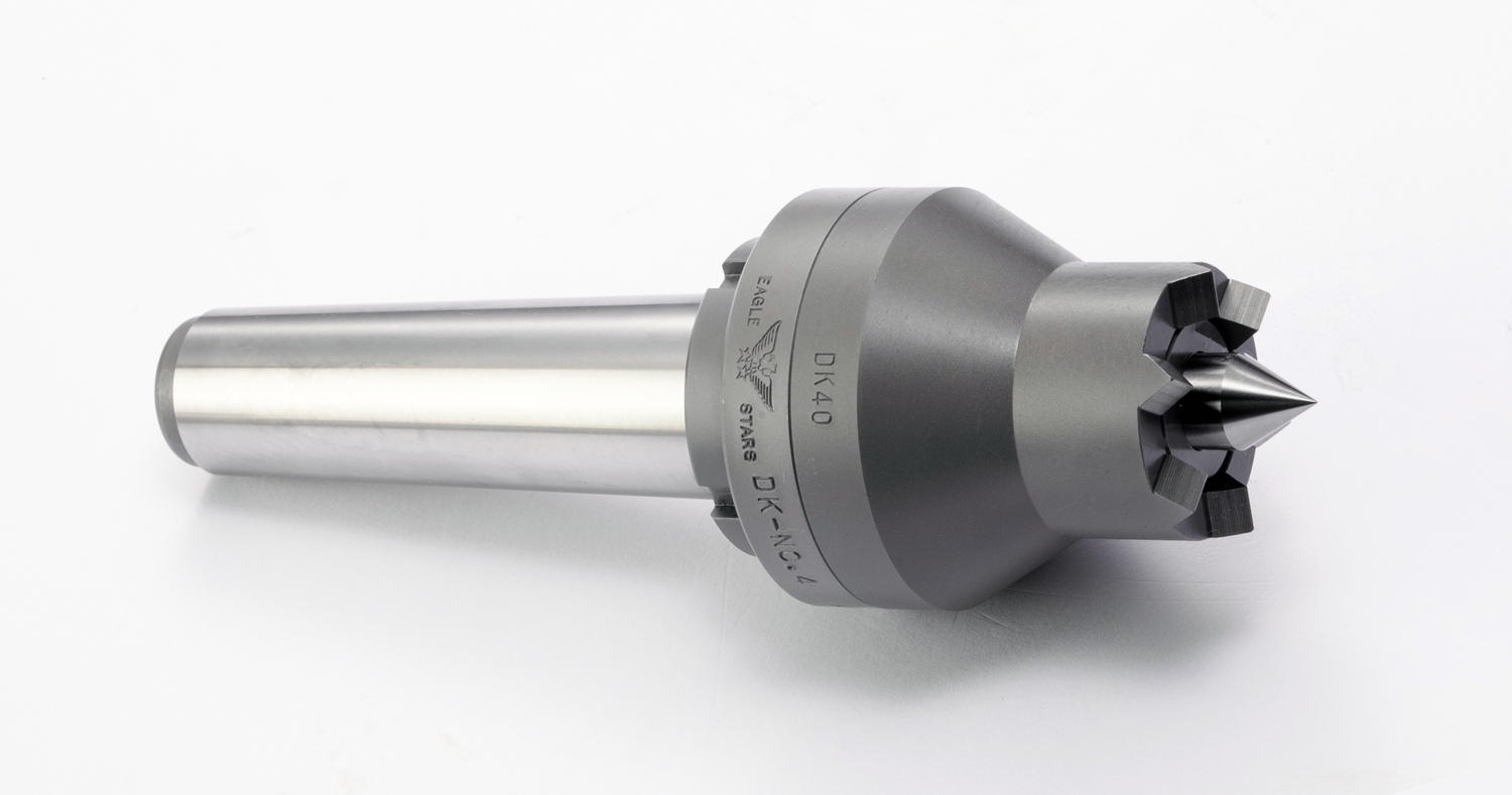
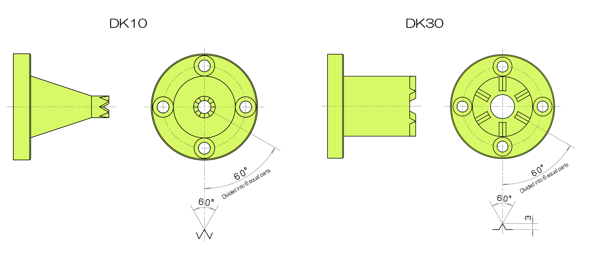
WORK-DRIVING CENTERS
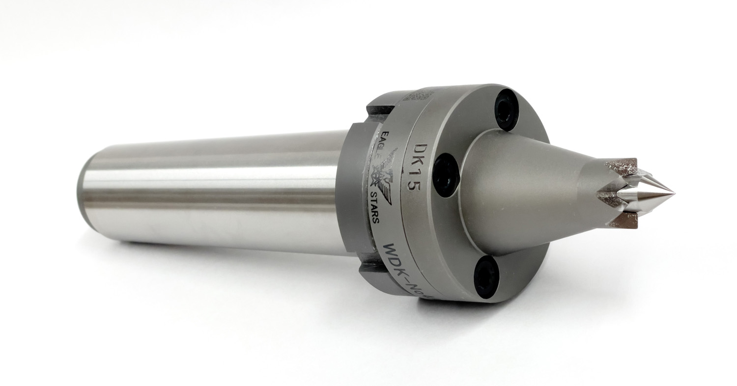
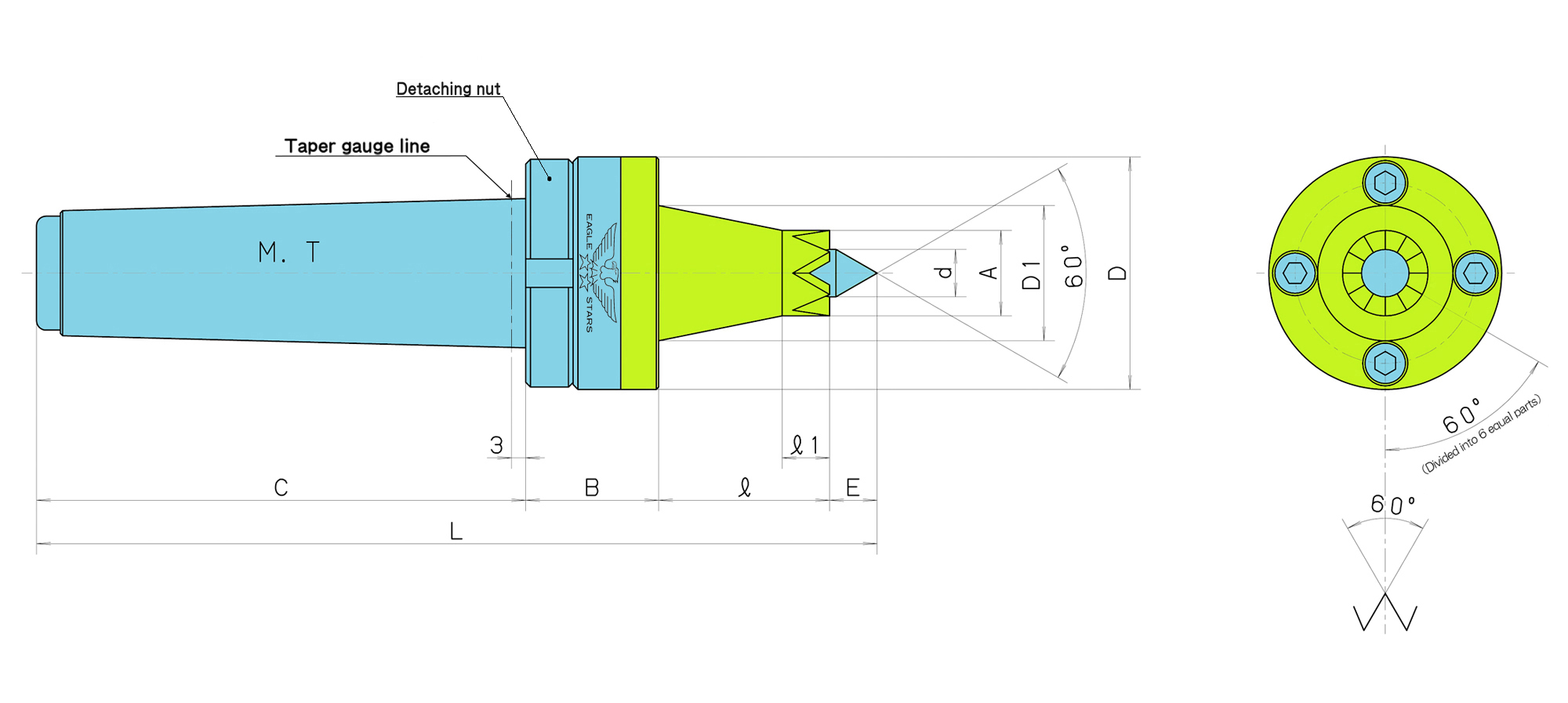
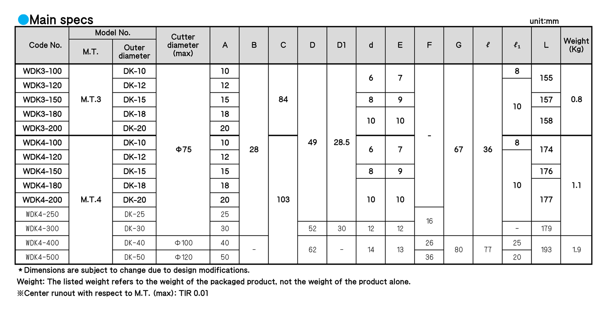
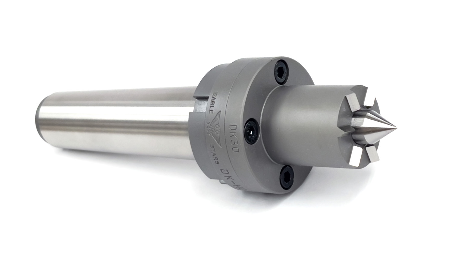
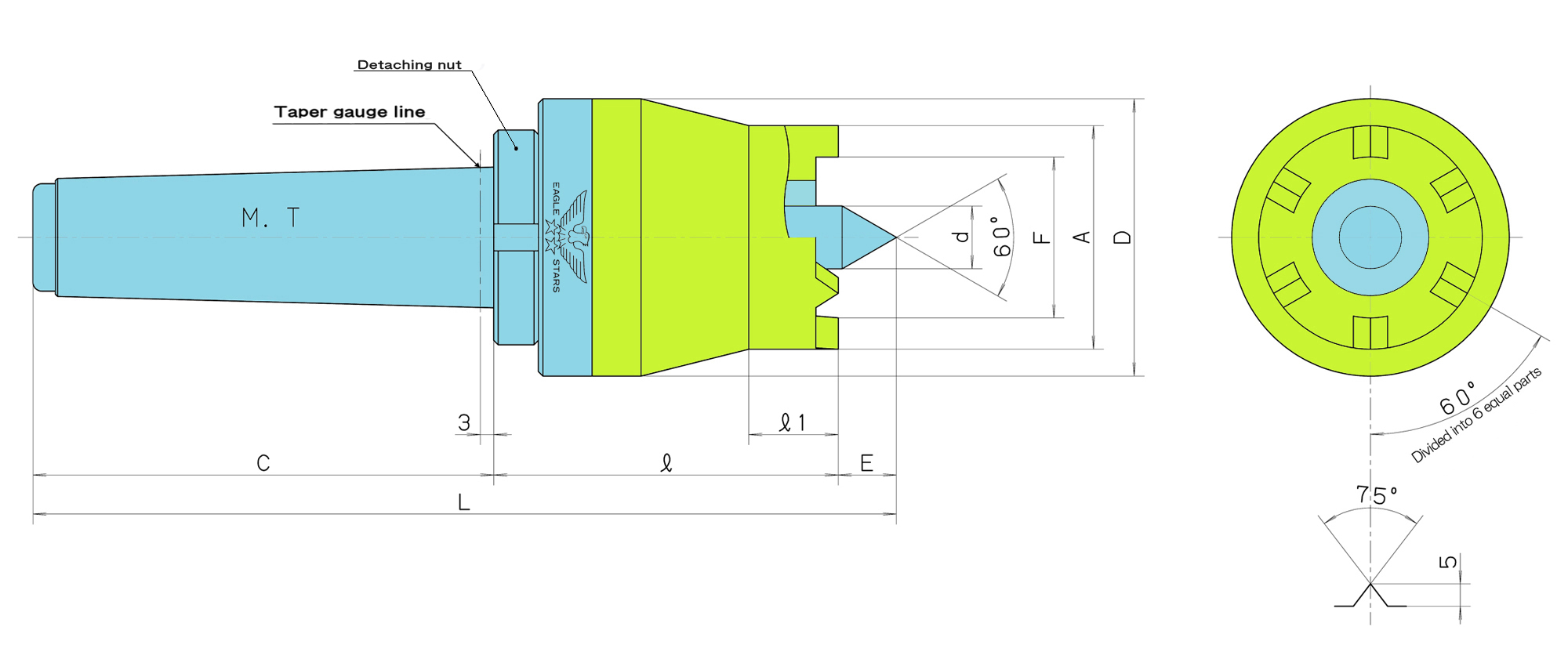
■ This model is suited for gear cutting, spline processing, keyway processing and woodworking.
■ Using this machine enables you to process without a chuck.
■ Since a workpiece is held by the two centers, the workpiece can be finished excellently.
■ A workpiece can be set and removed with a single touch.
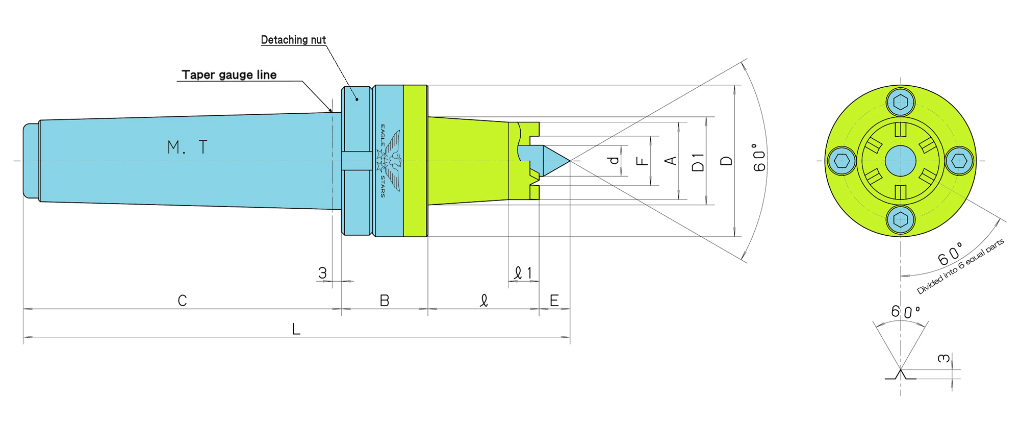
■ A detaching nut makes it easy to remove from the machine.
Regarding use
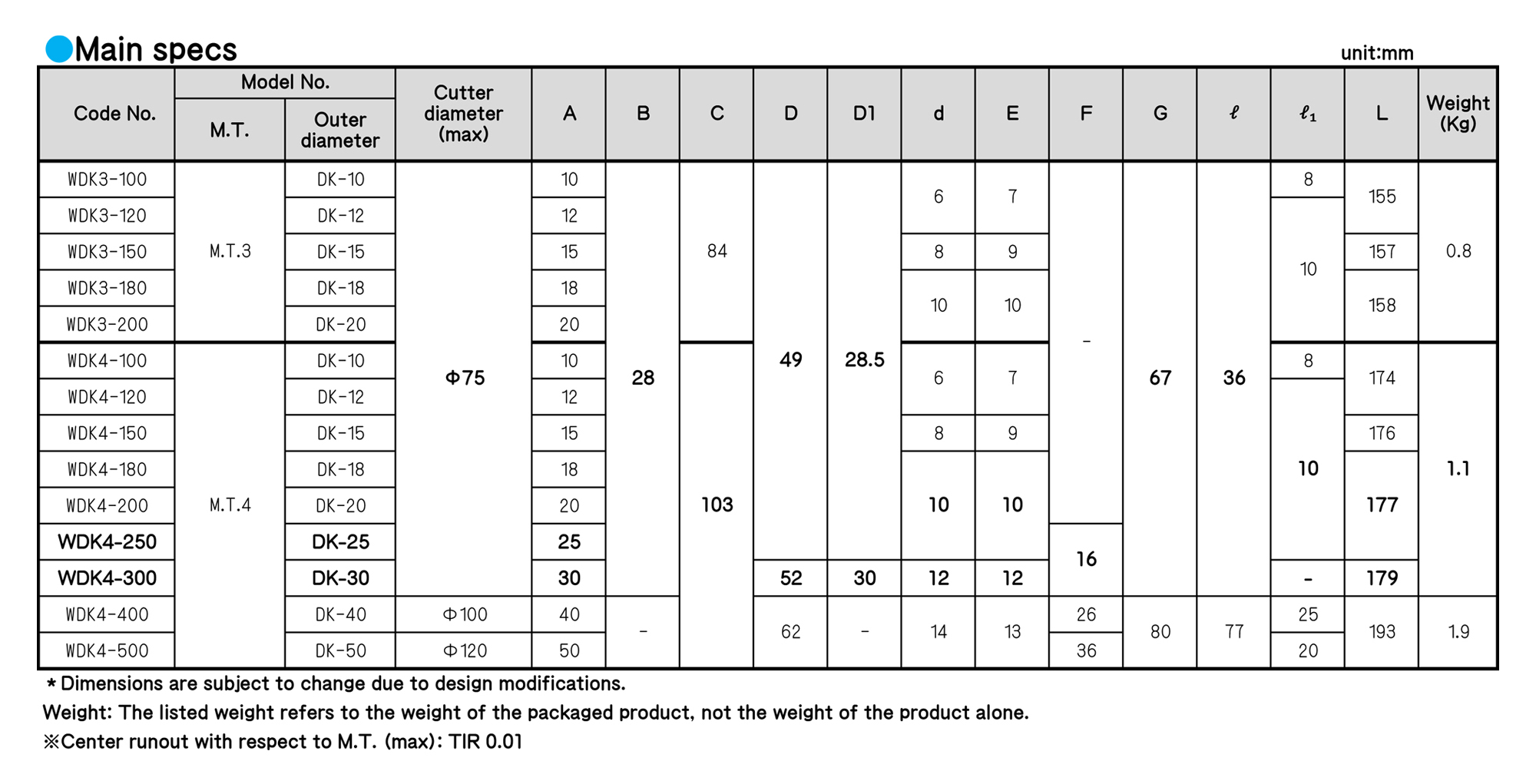
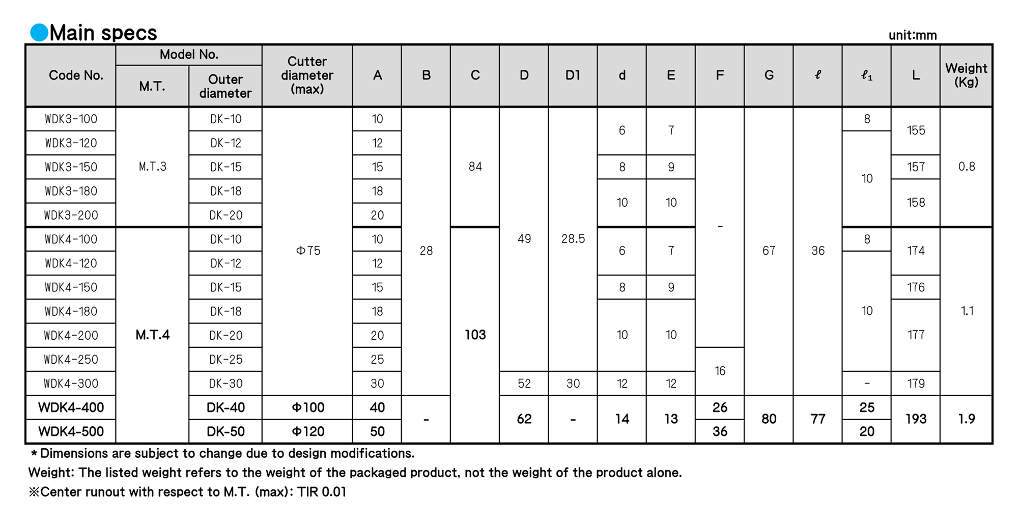
■ The maximum cutter diameter is φ75 for DK10 to DK30, φ100 for DK40 and φ120 for DK50.
■ If you want a special dimension, we will design and produce a product to meet the dimension, workpiece, drawings, etc. you provided.
■ If the jaws wear off or are damaged, we can supply spare jaws
■ The dimension of a hook spanner wrench for removal is for 45 to 50
WORK-DRIVING CENTERS
■ This model is suited for gear cutting, spline processing, keyway processing and woodworking.
■ Using this machine enables you to process without a chuck.
■ Since a workpiece is held by the two centers, the workpiece can be finished excellently.
■ A workpiece can be set and removed with a single touch.
■ A detaching nut makes it easy to remove from the machine.
Regarding use
■ The maximum cutter diameter is φ75 for DK10 to DK30, φ100 for DK40 and φ120 for DK50.
■ If you want a special dimension, we will design and produce a product to meet the dimension, workpiece, drawings, etc. you provided.
■ If the jaws wear off or are damaged, we can supply spare jaws
■ The dimension of a hook spanner wrench for removal is for 45 to 50
WORK-DRIVING CENTERS
■ If a jaw of work-driving center wears off or is damaged, please replace it with a spare jaw immediately.
■ When ordering a spare jaw, please check the rotational direction (type) of the machine.
Regarding the rotational direction
Choose the counterclockwise direction “R (normal rotation)” or the clockwise direction “L (inverse rotation),” seeing the spindle (main shaft).
WORK-DRIVING CENTERS
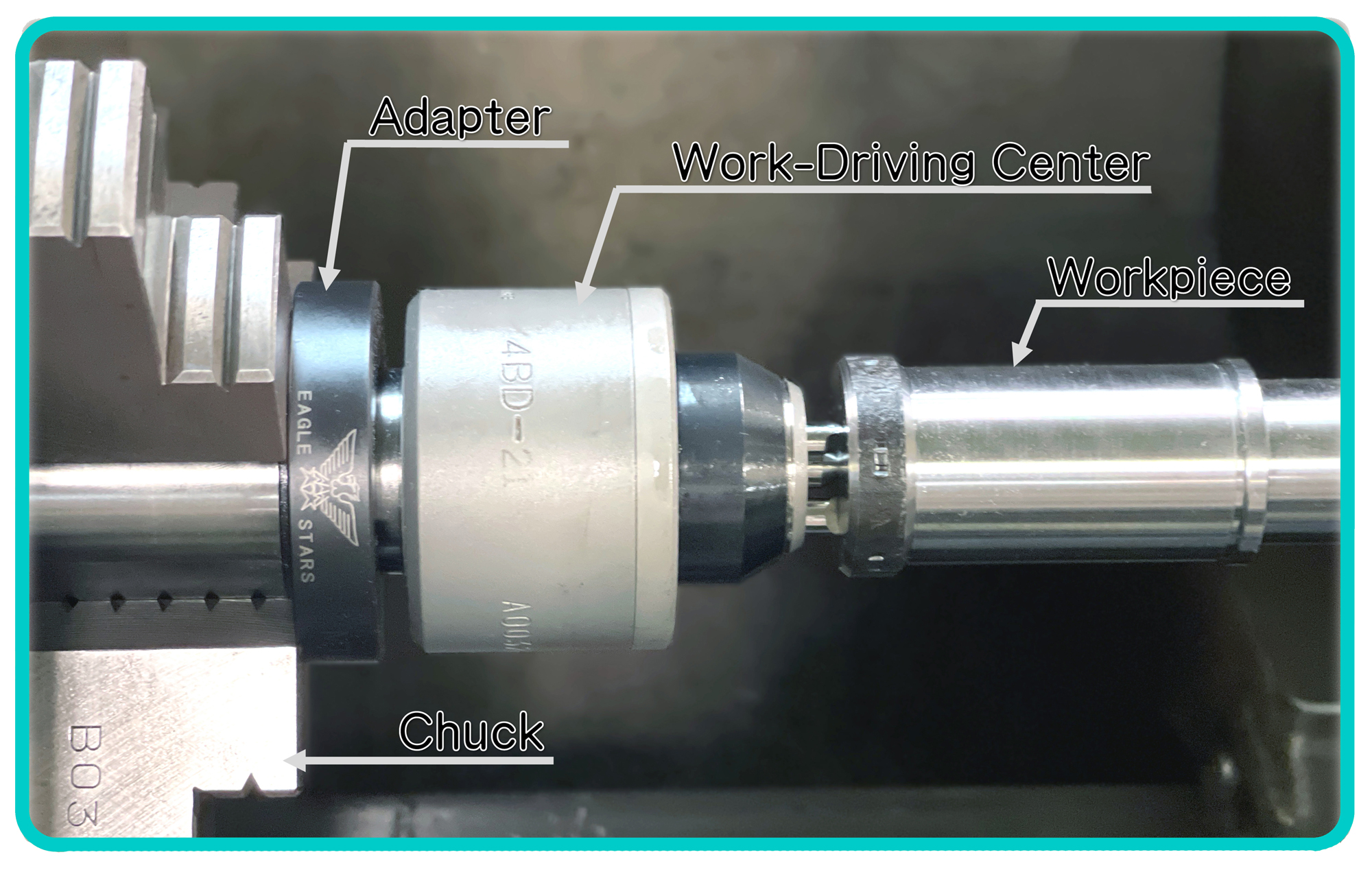
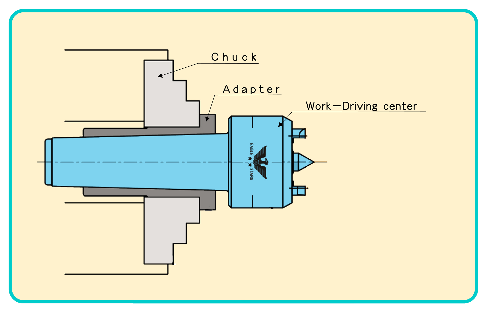
■ The outer part (gripping part) is straight to make it easy to use for NC machines If you use a wert- driving center in conjunction with an adapter, you do not need to remove it from a chuck,The outer part of the adapter is gripped by the soft jaws of the chuck. (All products are quenched and polished ones.)
Regarding use
■ After driving a work-driving center into the adapter, grip it by the soft jaws of the chuck.
■Please use after checking the precision of work – driving center which is driven into an adapter,
WORK-DRIVING CENTERS
Custom-made products
Flange type
Made-to-order product
WORK-DRIVING CENTERS
Reference for combination chuck
Made-to-order product
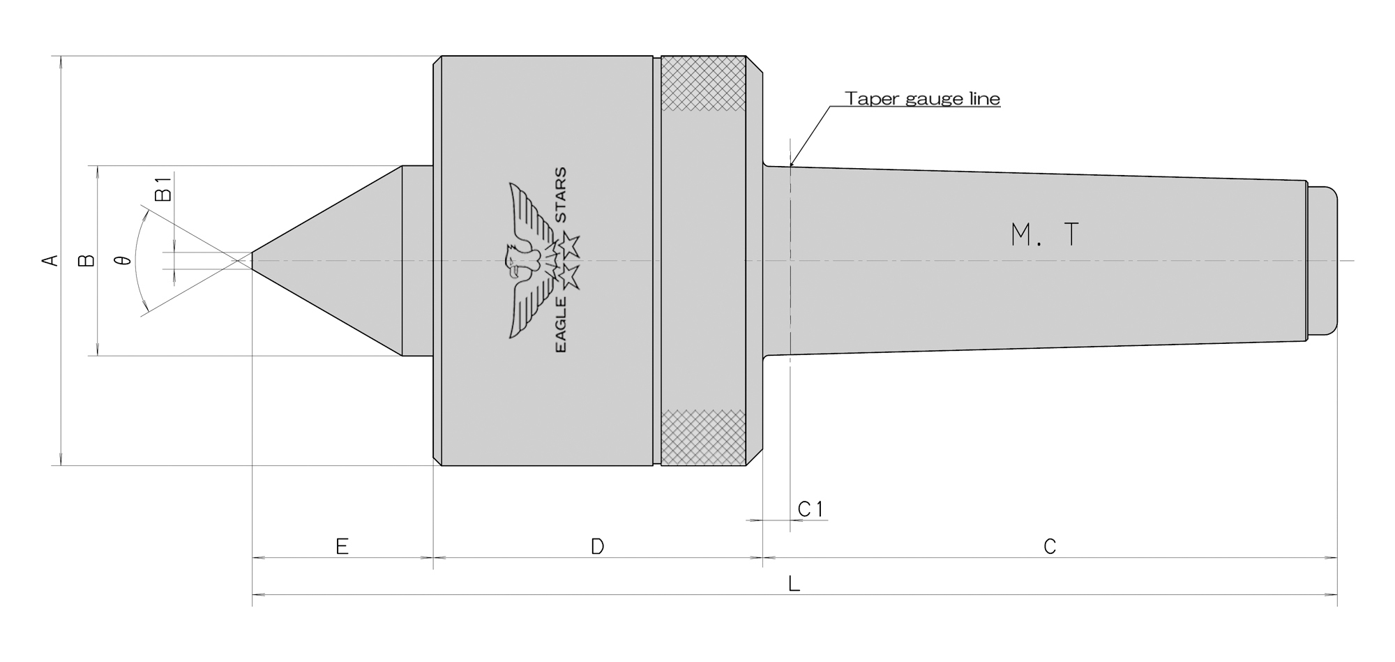
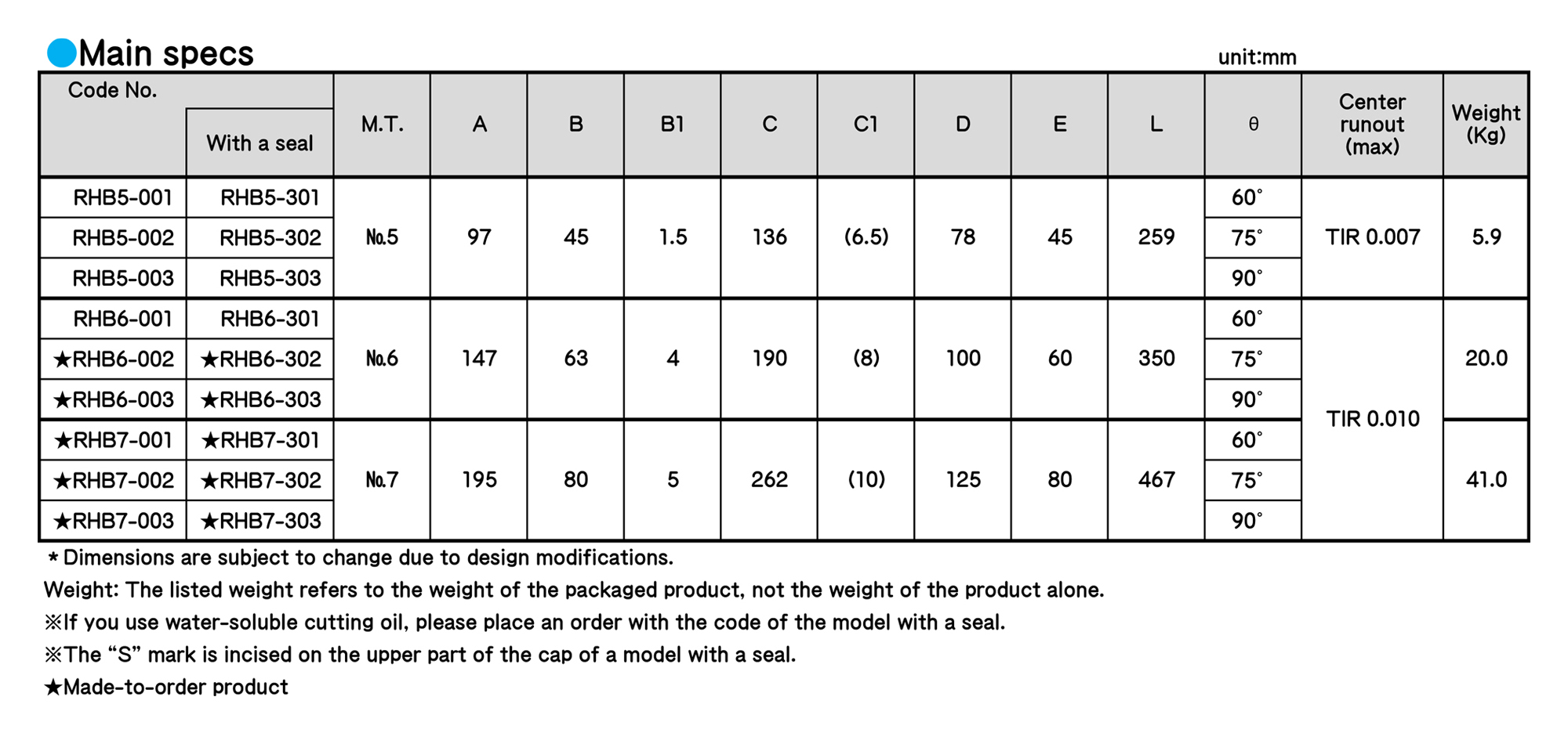
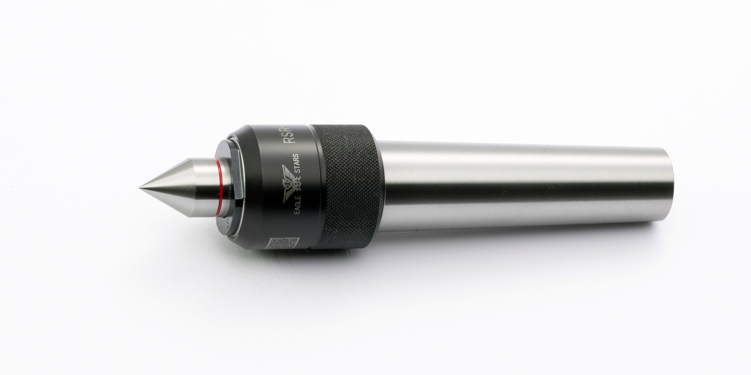
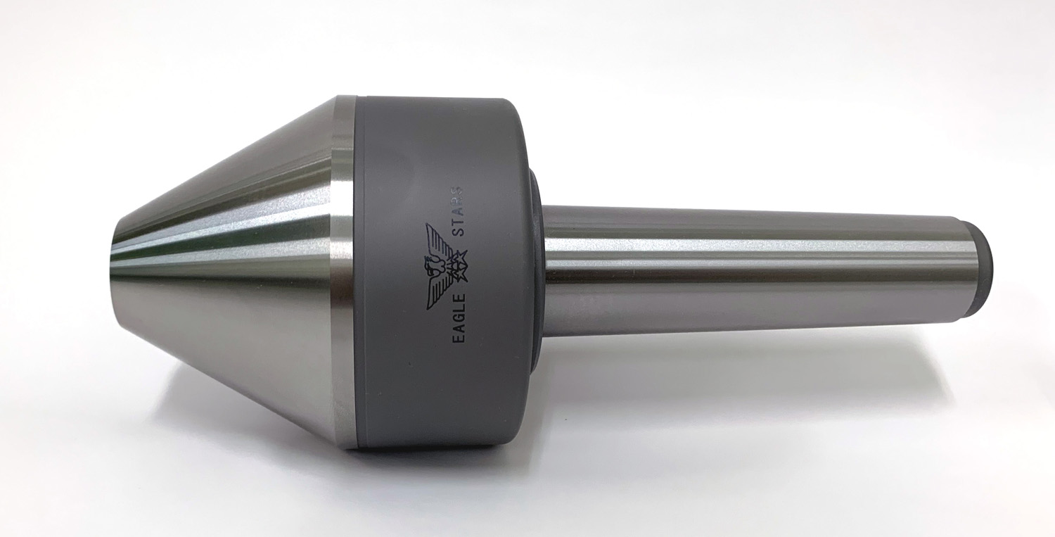
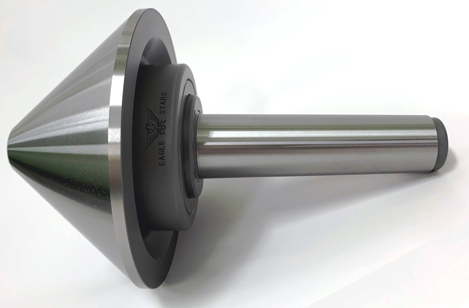
BEVEL ROLLING CENTERS
BEVEL ROLLING CENTERS
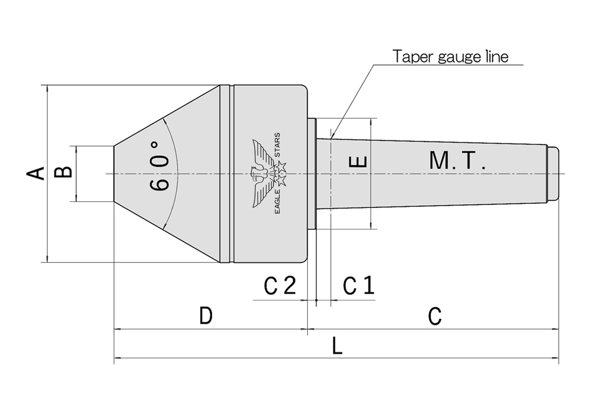
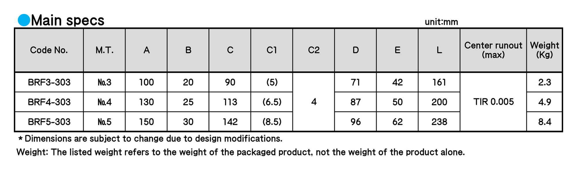
BEVEL ROLLING CENTERS
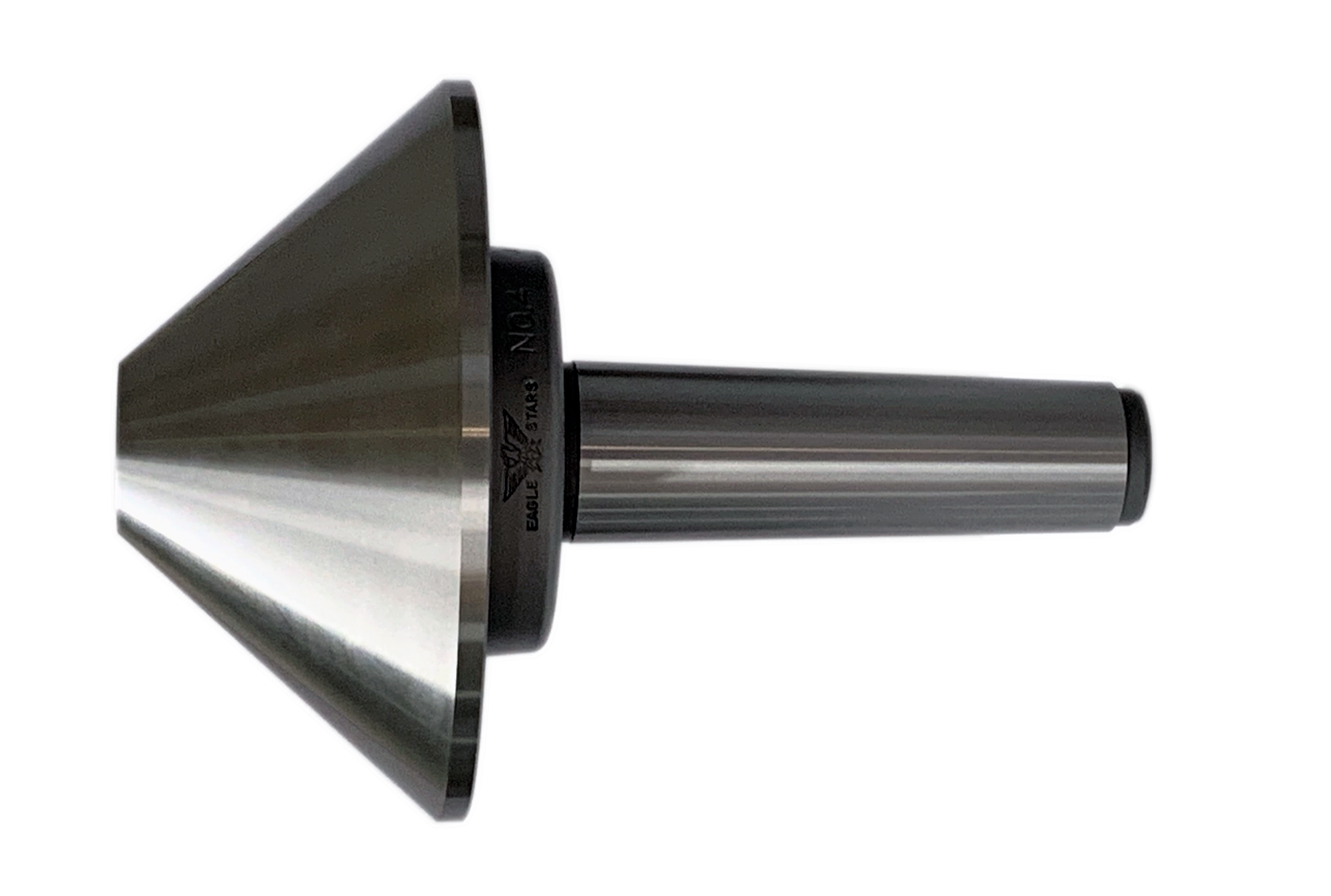
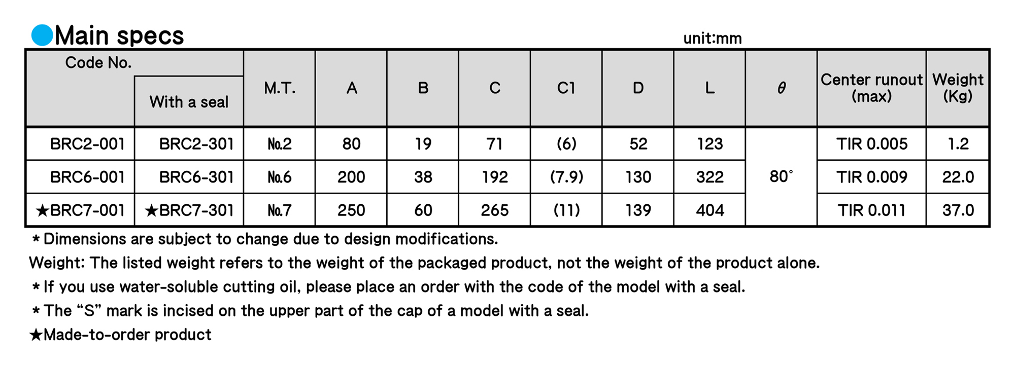
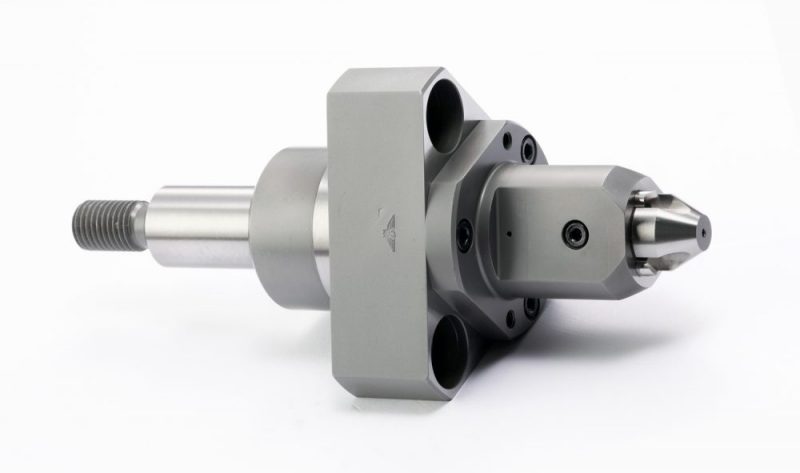
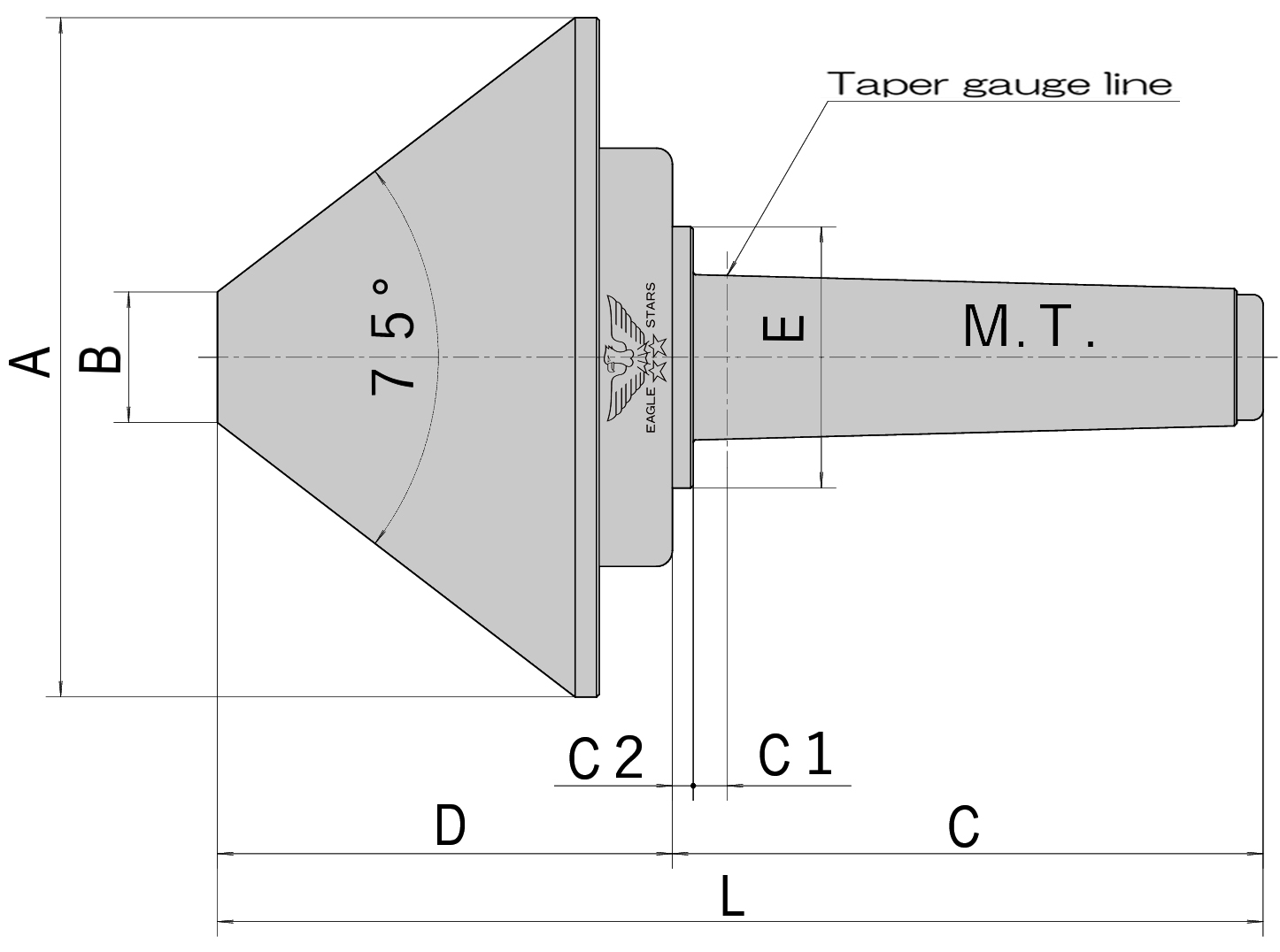
■ Used for pushing a center for pipe-shaped, ring-shaped and thin workpieces.
■ For the inside of this product, a tapered roller bearing, a thrust bearing and a ball bearing are used.
◆ If you use a center for grinding machines, we will produce a high-precision center for an angular bearing.
◆ For some machines you use or grinding machines, the C1 dimension between the standard taper diameter and the body is large.
In this case, the shank part is special. Please notify us of the dimension.
※Caution: This product cannot be used for a tailstock with a detaching nut.
If a detaching nut is attached to the tailstock of the machine you use, you cannot use the detaching nut.
Due to structural characteristics, the body part may be detached from the M.T. shank part. In this case, we will produce a custom order product and please notify us.
Please do not let the M.T. shank side of the head part (rotation part) be hit, shocked, or the like. There is a risk that the head part will be detached from the shank part.
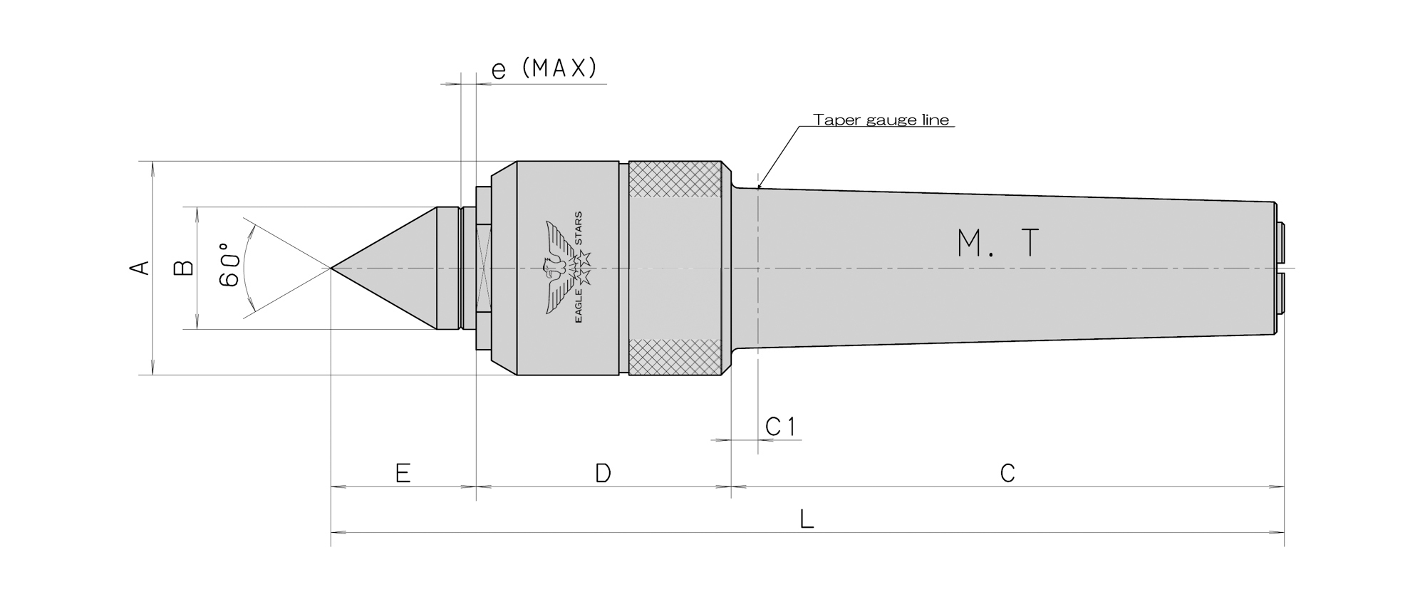
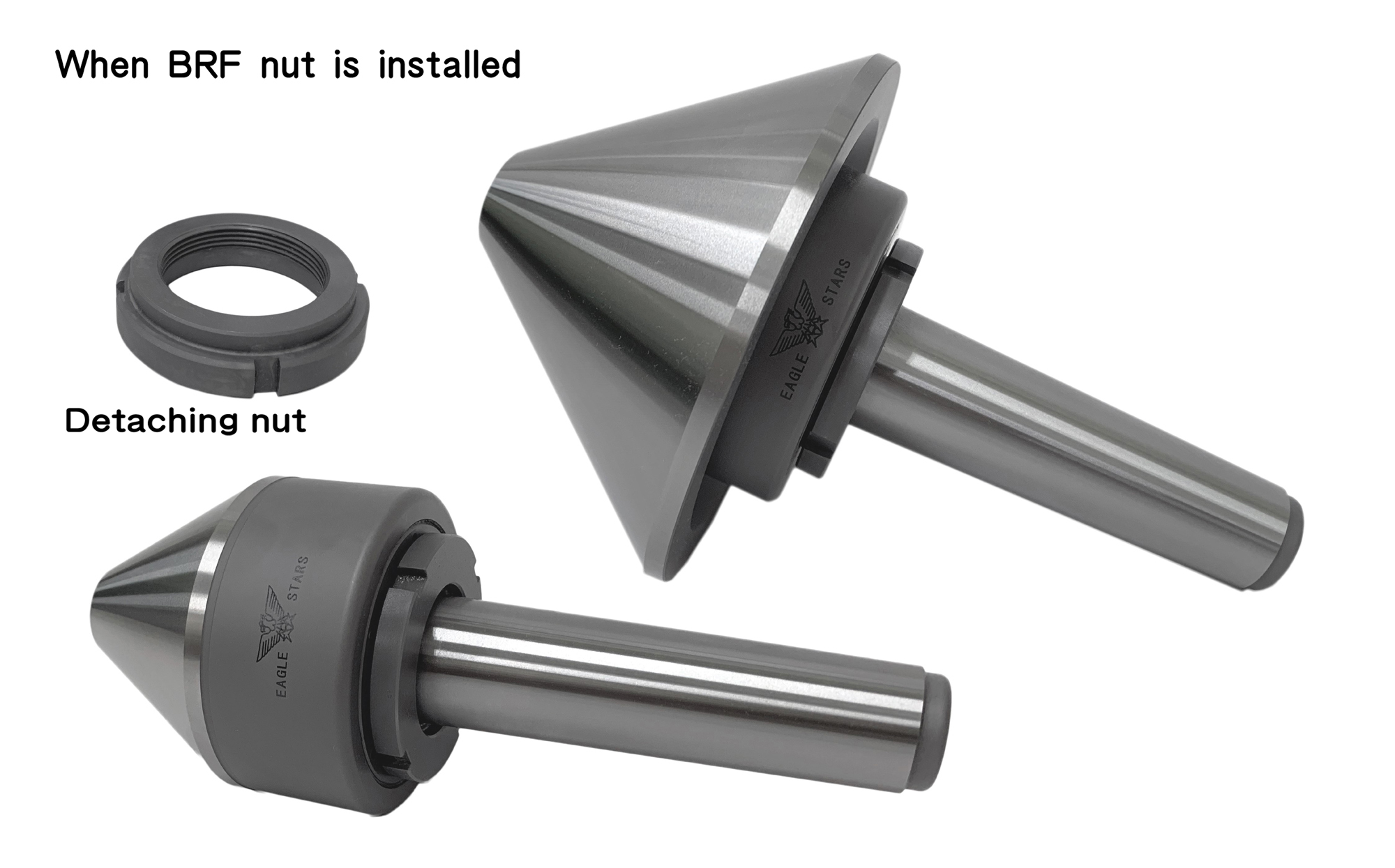
BEVEL ROLLING CENTERS

■ Used for pushing a center for pipe-shaped, ring-shaped and thin workpieces.
■ This model is equipped with a watertight seal.
■ It is compatible with removal from a tailstock with a detaching nut.
■ For the inside of this product, a tapered roller bearing, a thrust bearing and a needle bearing are used.
■ It is possible to attach a detaching nut as an option.
◆ If you use a center for grinding machines, we will produce a high-precision center for an angular bearing.
◆ For some machines you use or grinding machines, the C1 dimension between the standard taper diameter and the body is large. In this case, the shank part is special. Please notify us of the dimension.
BEVEL ROLLING CENTERS
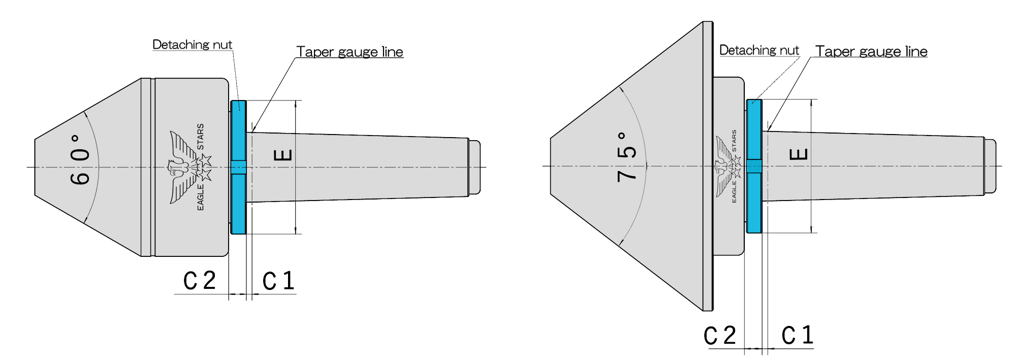
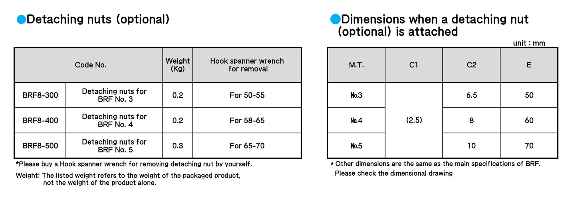
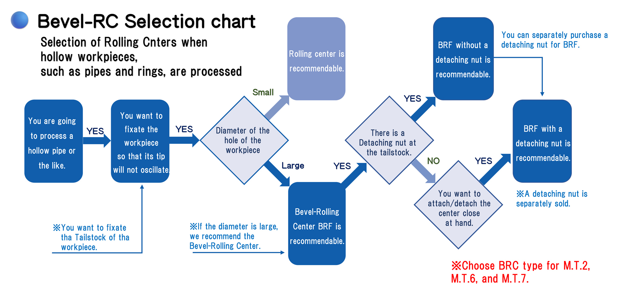
BEVEL ROLLING CENTERS
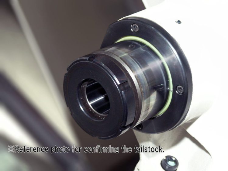
■ Please check if there is a detaching nut for the tailstock.
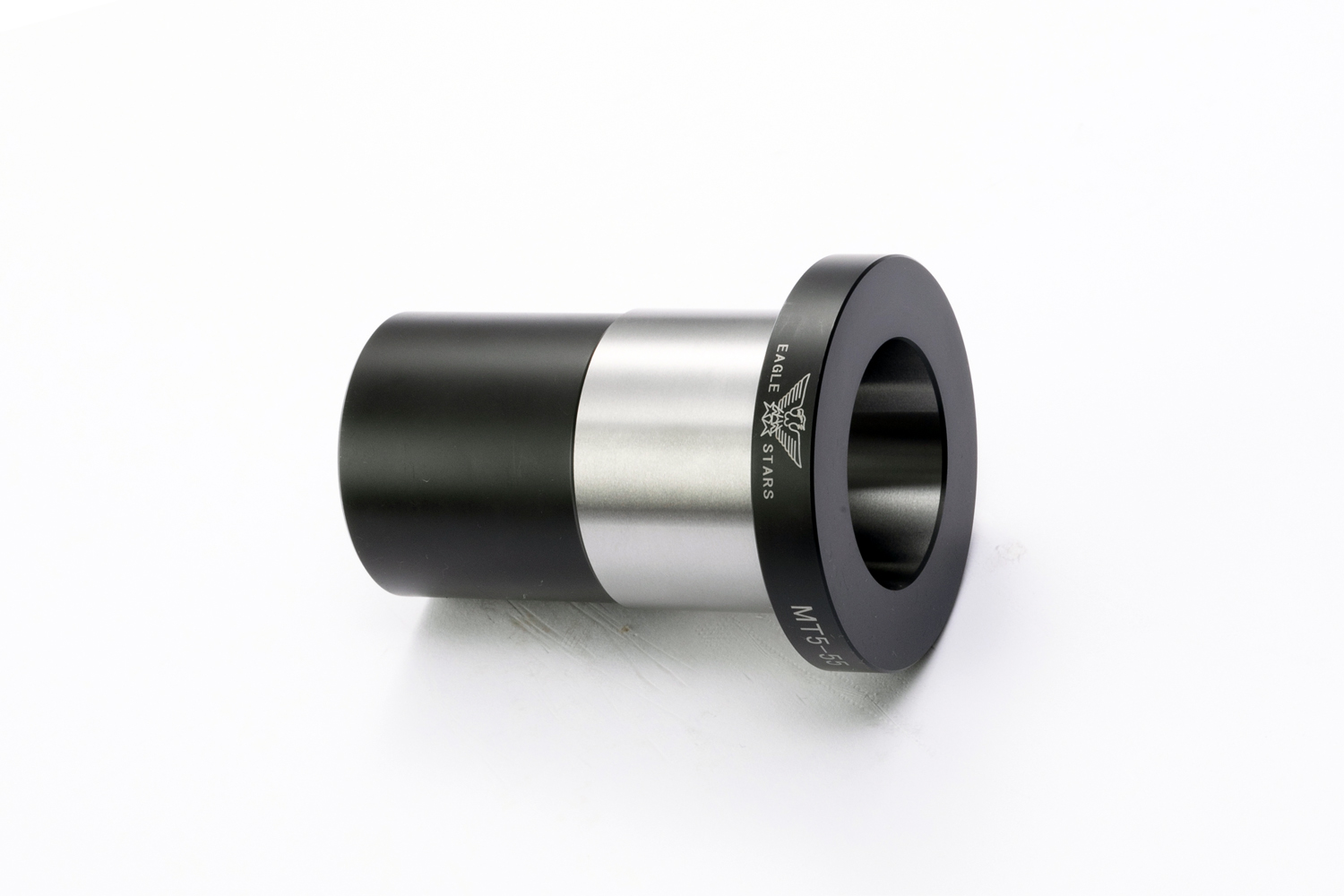
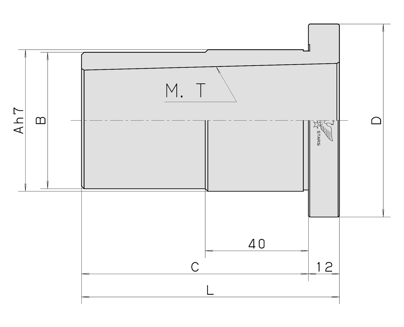
LATHE CENTERS
LATHE CENTERS
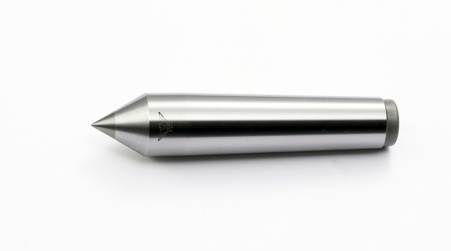
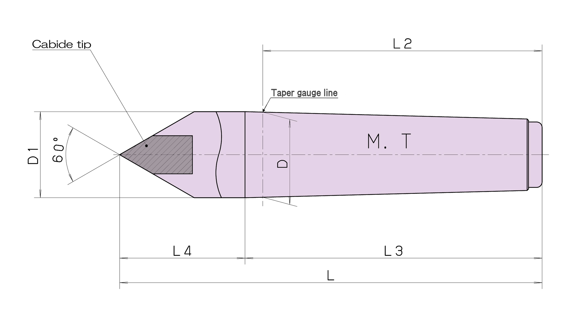
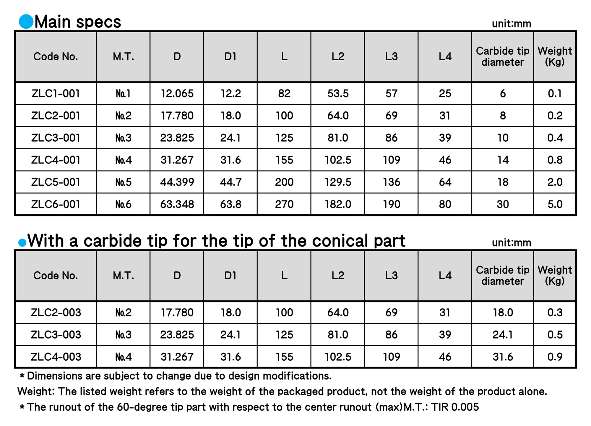
■ Used for machines and cylindrical grinding machines.
■ We can also produce lathe centers mounted with a specially shaped tip, a ring-shaped tip or a removable nut, or a lathe center with an extended overall length, if ordered separately.
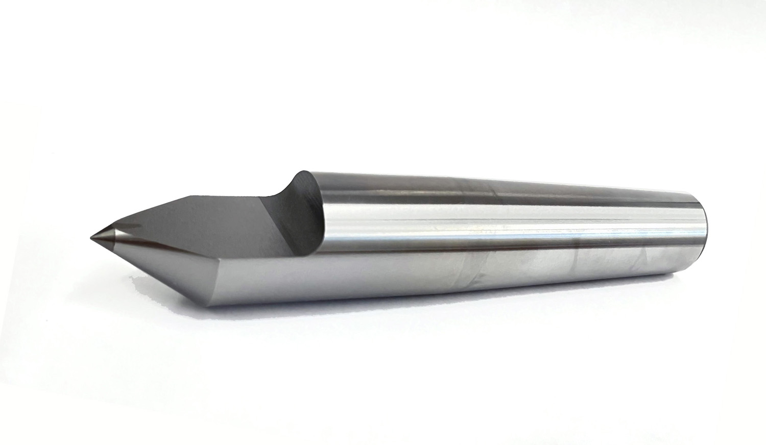
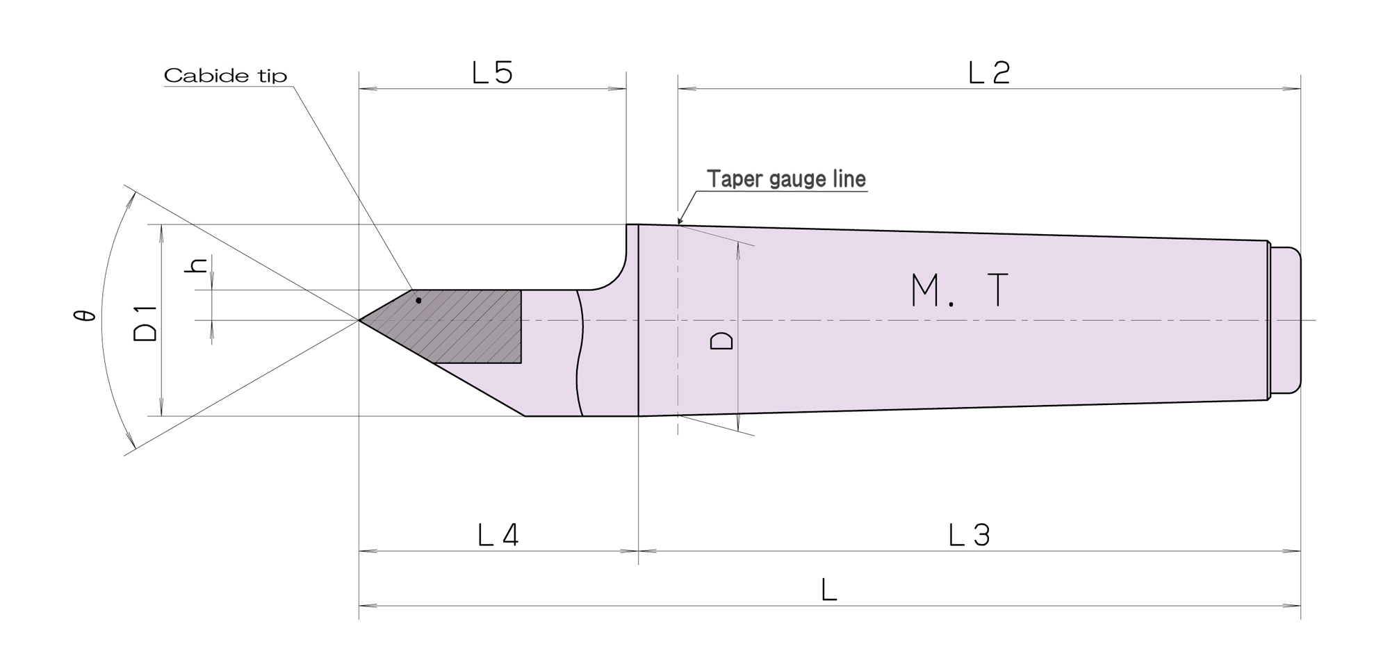
LATHE CENTERS
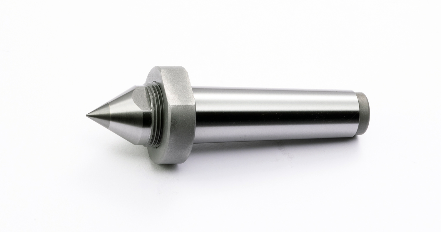
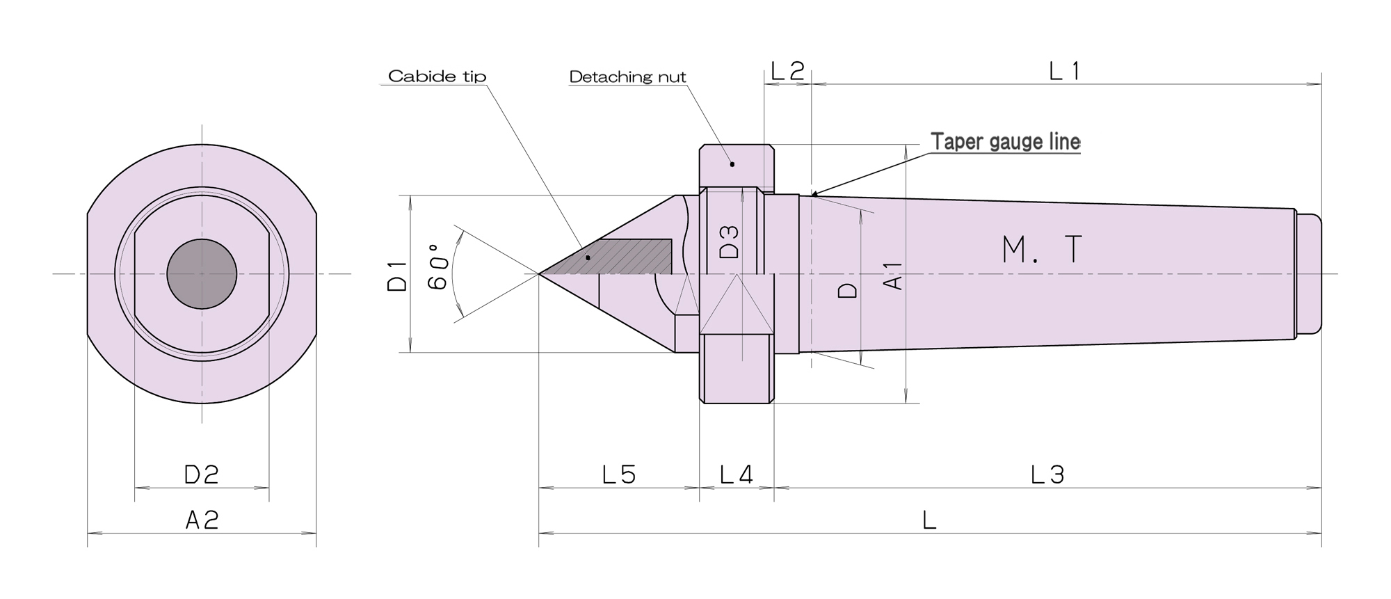
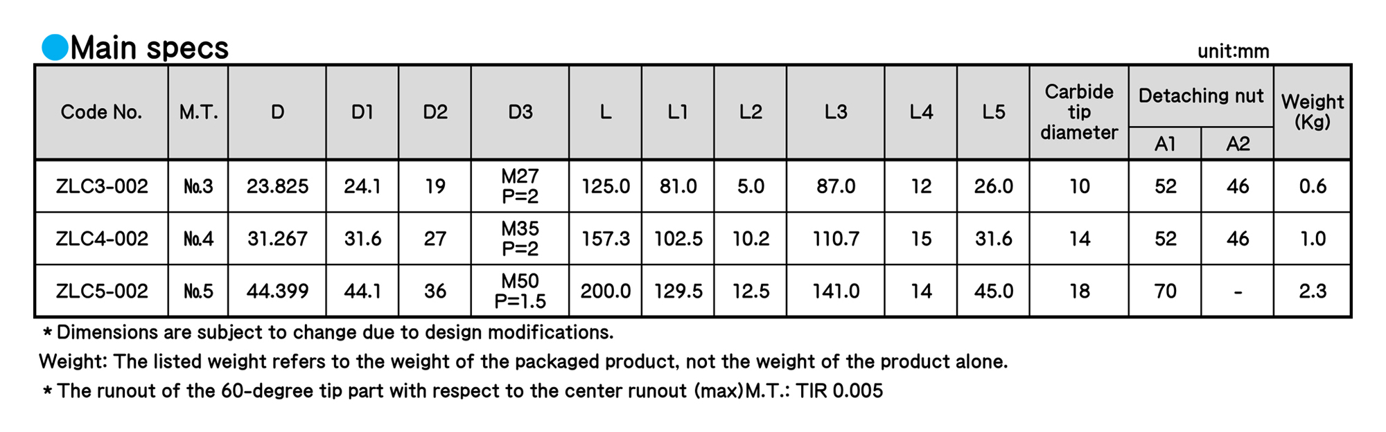
■ Since a lathe center is mounted with a detaching nut, this machine can be detached from the front part of the tailstock easily.
■ Used for a built-in tailstock.
■ A special shape is available, through a custom order.
■ When ordering a special shape, please notify us of the maker and model of your machine.
◆ As for hook spanner wrenches for the detaching nut ZLC5-002 (M.T.5), please use the commercially available products for 70 to 75.
LATHE CENTERS
information/other
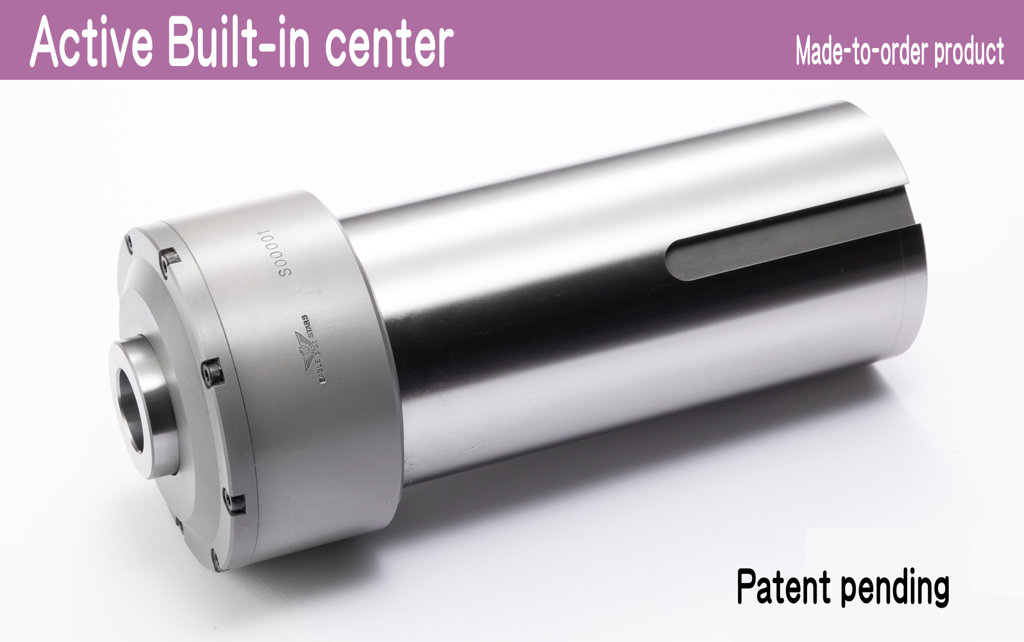
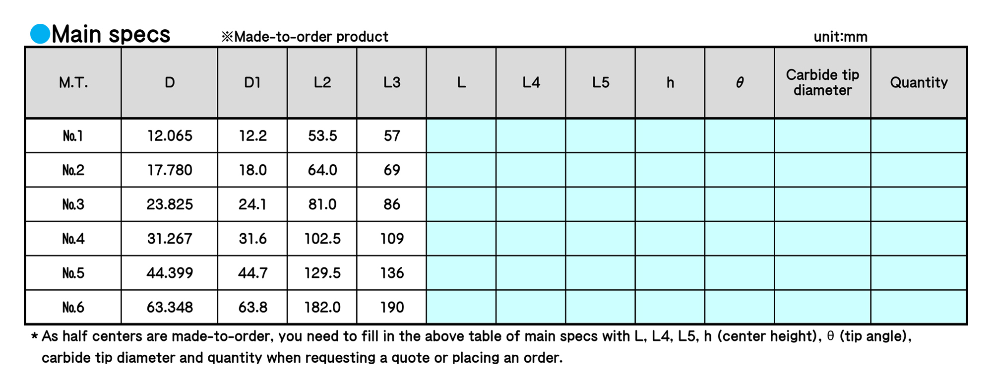
Active Built-in center (Made-to-order product) 【Patent pending】
Futamura Machines & Tools offers a long-awaited new built-in center that can handle the demands of high-rigidity lathe machining. A built-in center that is the culmination of the center Manufacturer’s proprietary know-how. Makes customer machining processes more dynamic and satisfying.
information/other
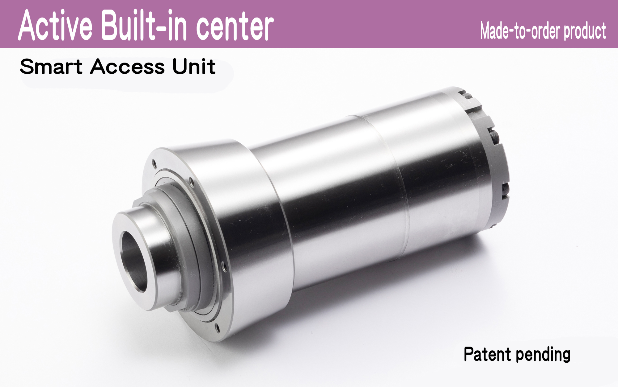
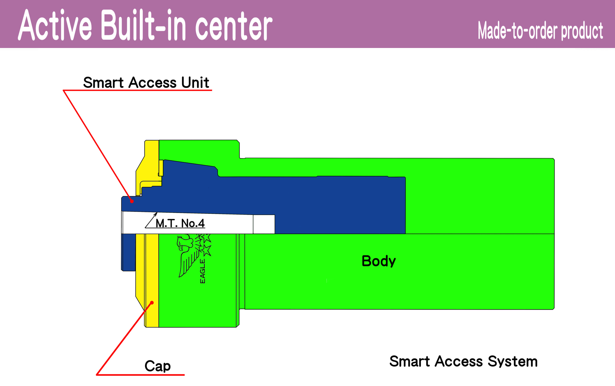
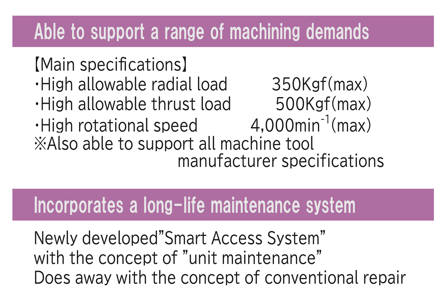
Active Built-in center replacement unit (Made-to-order product)【Patent pending】
“Smart Access System”
The average life of a built-in center is approximately 3 to 4 years.
Typically, the repair of built-in centers has required large-scale operations by machine tool manufacturer workers.
The “Smart Access System” is an innovative system that allows the Smart replacement of the rotating unit, the heart of the built-in center, as if it were a rotating center.
This system reduces the average replacement time to only a few hours, contributing to dramatic process improvements.
Futamura Machines & Tools offers a long-awaited new built-in center that can handle the demands of high-rigidity lathe machining. A built-in center that is the culmination of the center Manufacturer’s proprietary know-how. Makes customer machining processes more dynamic and satisfying.
information/other
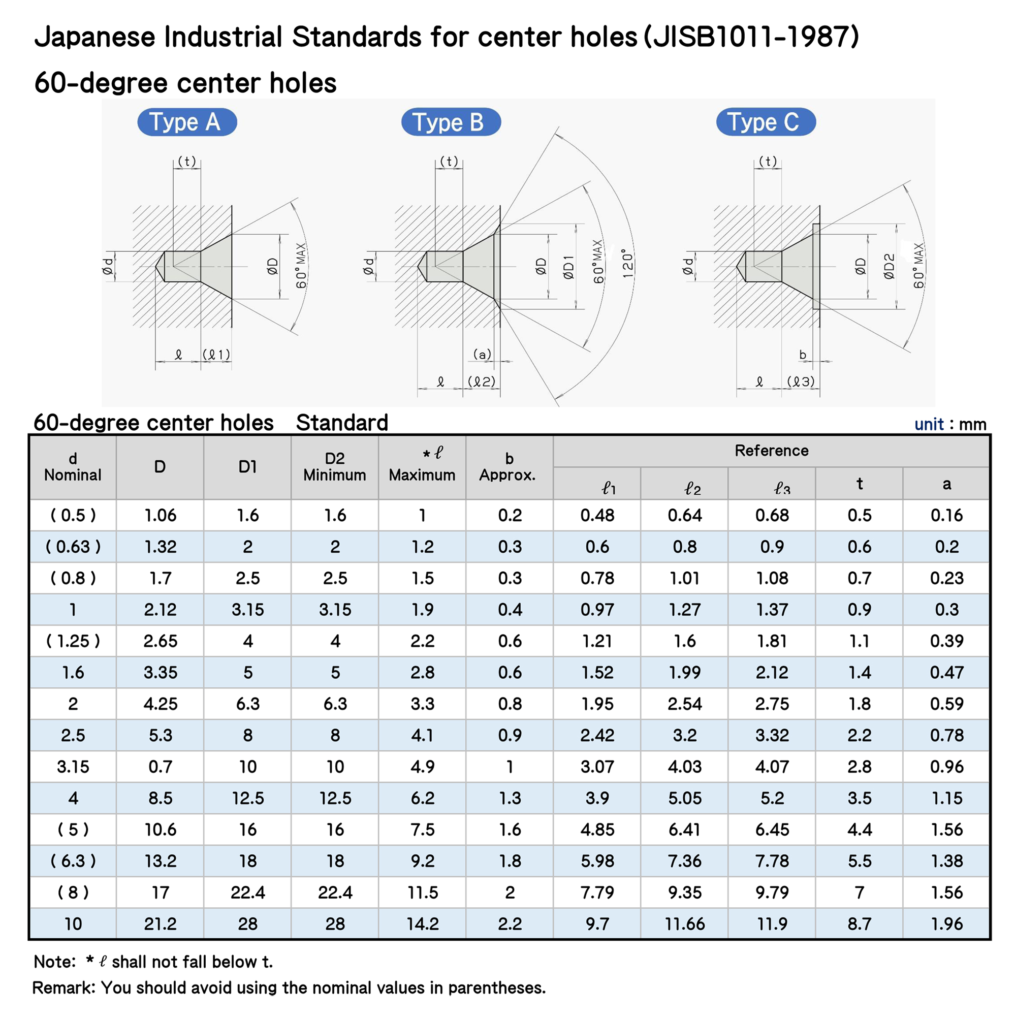
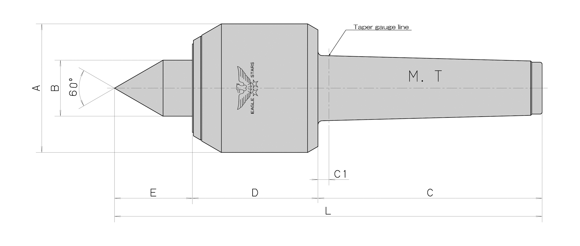
Japanese Industrial Standards for center holes(JISB1011-1987)
60-degree center holes
Please finish the center hole so that its shape and dimension are appropriate.
In order to bring out the processing performance of eagle-mark products to a sufficient degree, it is necessary to finish the center hole of each workpiece so that its shape and dimension are appropriate.
Differing from the dimension of a workpiece, the dimension of its center hole may be limited according to the purpose of use. Please be careful so that the center hole dimension satisfies the JIS standard.
information/other
